4.4
Description of
the steering system
4.4.1
Physical description
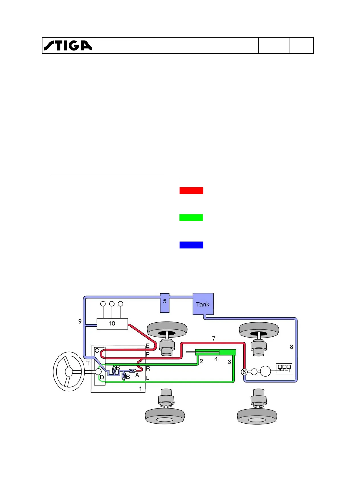
1.
Power steering servo containing the
following:
A. Pressure relief valve
B. Safety valves
C. Control module
D. Oil pump
Connections on power steering servo
P. Unregulated input from hydraulic
pump for external hydraulics.
T. Output to the tank for tramp oil and
return oil from the passive side of the
steering cylinder when steering.
E. Output to other external hydraulics.
L. Output to steering cylinder. Pres-
sure when steering to left.
R. Output to steering cylinder. Pres-
sure when steering to right.
2, 3.Pressure lines for transferring steer-
ing force.
4.
Steering cylinder.
5.
Collector block.
6.
Pump for external hydraulics, integrat-
ed with the drive pumps.
7.
Pressure line.
8.
Suction line.
9.
Tramp oil line and return line.
10.External hydraulics.
Colour - Pressure
Red displays the supply pres-
sure to the power steering servo
and external hydraulics.
Green can be both the pressure
line and the return line, depend-
ing on the movement.
Blue displays the atmospheric
pressure in the oil reservoir and
lines.
WORKSHOP MANUAL
TITAN
Chapter
4 - Hydraulic system
EDITION
2018
Page
52
 Loading...