4.6.2
Function description
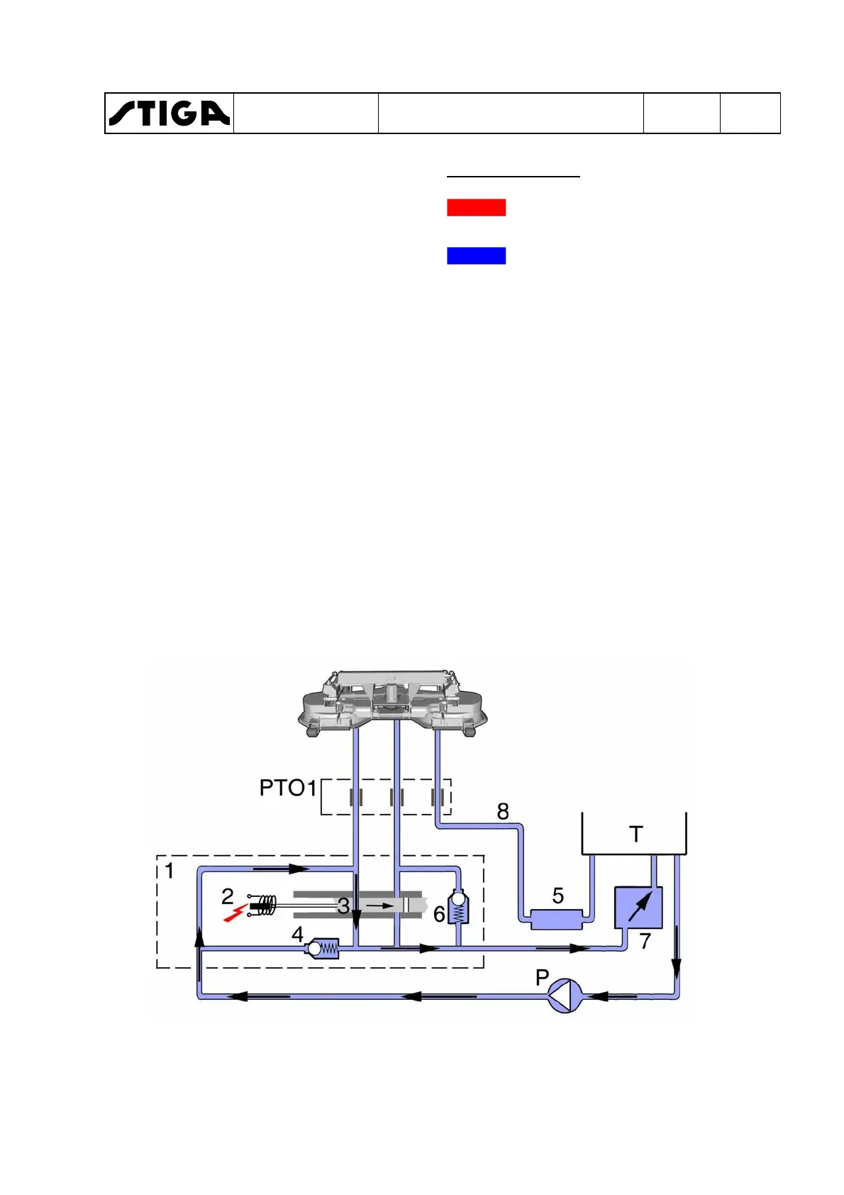
No drive engaged
1.
PTO valve, including 2, 3, 4 and 6 be-
low.
2.
Electric solenoid.
3.
Slide inclusive right and left valve.
4.
Pressure limiter valve, 220 bar.
5.
Collector block.
6.
Brake valve, 10 bar.
7.
Oil cooler.
8.
Tramp oil line.
P. Hydraulic pump.
PTO1. Hydraulic socket .
PTO1s.Switch.
T. Tank.
Colour - Pressure
Red displays the supply pres-
sure to the implement.
Blue displays the atmospheric
pressure in the return lines.
The solenoid is unpowered and the slide
is in wait mode. Left valve is open and
right valve is closed.
The pump pumps oil, which passes the
left valve and returns to the tank via the
oil cooler.
Only slight pressure remains in the lines
depending on the resistance in the lines
and valve.
WORKSHOP MANUAL
TITAN
Chapter
4 - Hydraulic system
EDITION
2018
Page
71
 Loading...