4.5.2
Physical description
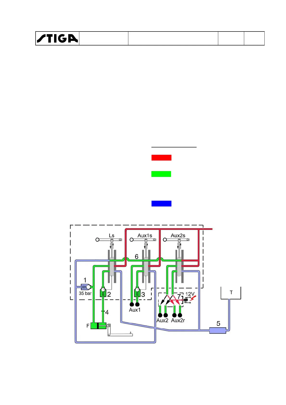
F. Cylinder implement lift.
Ls.Controls for implement lift F.
Aux1. Hydraulic socket front, located to
the left.
Aux1s.Control for hydraulic socket Aux1.
Aux2. Hydraulic socket front, located to
the right.
Aux2r.Hydraulic socket rear (not availa-
ble on all models).
Aux2s.Control for hydraulic sockets Aux2
and Aux2r.
T. Tank.
Also see the next page for location on the
machine and further description of the
components.
1.
Pressure relief valve.
2.
Mechanically affected non-return
valve.
3.
Mechanically affected non-return
valve.
4.
Limit valve lowering.
5.
Collector block.
6.
By-pass line.
7.
Electric valve, controlled by Aux2fr
(not available on all machines).
Colour - Pressure
Red displays the supply pres-
sure to the external hydraulics.
Green can be both the pressure
line and the return line, depend-
ing on the implement move-
ment.
Blue displays the atmospheric
pressure in the return lines.
Valve block
WORKSHOP MANUAL
TITAN
Chapter
4 - Hydraulic system
EDITION
2018
Page
59
 Loading...