P
PTO1s
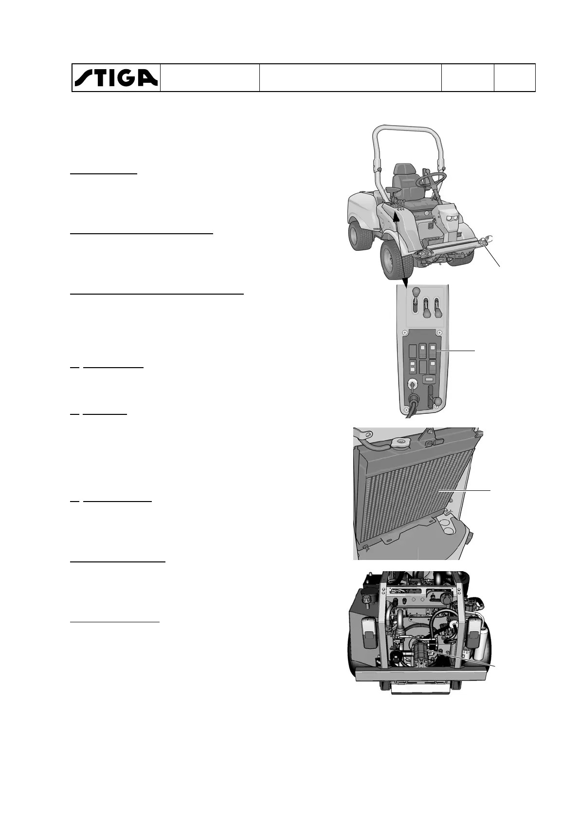
Location of controls and hydraulic
sockets on the machine
For position see page 70.
1. PTO valve
The PTO valve is an integrated unit
that contains all the properties re-
quired to drive the accessory.
2. Electric solenoid, 3. Slide
These parts are mechanically con-
nected. The solenoid is affected by
the switch PTO1s.
4. Pressure limiter valve, 125 bar.
The pressure limiter valve ensures
that the pressure never exceeds 125
bar, for example if the rotating parts
are blocked.
6.
Brake valve
The brake valve minimises the imple-
ment stop time.
7.
Radiator
The PTO oil always passes the oil
cooler when the engine is running.
Because the same oil is used for driv-
ing, the hydraulic oil is kept at a suita-
ble temperature level.
8.
Tramp oil line
The tramp oil line transports all tramp
oil from the implement motor back to
the tank via the collector block.
P. Hydraulic pump
The hydraulic pump is directly con-
nected to the engine and works all the
time that the engine is running.
5. Collector block
The collector block collects all tramp
oil and return oil from the hydraulic
TO1
7
components and returns it to the tank.
P
WORKSHOP MANUAL
TITAN
Chapter
4 - Hydraulic system
EDITION
2018
Page
70
 Loading...