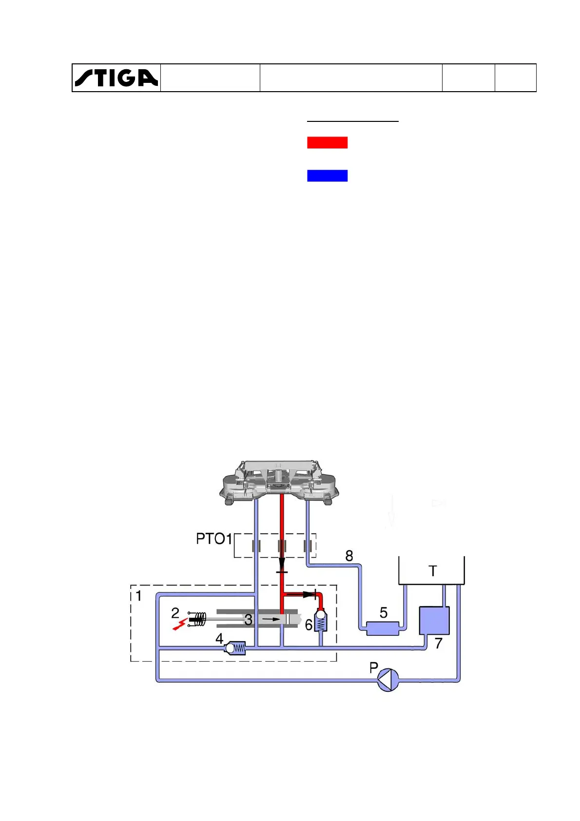
Brake function
1.
PTO valve, including 2, 3, 4 and 6 be-
low.
2.
Electric solenoid.
3.
Slide inclusive right and left valve.
4.
Pressure limiter valve, 220 bar.
5.
Collector block.
6.
Brake valve.
7.
Oil cooler.
8.
Tramp oil line.
P. Hydraulic pump.
PTO1. Hydraulic socket .
PTO1s.Switch.
T. Tank.
Colour - Pressure
Red displays the supply pres-
sure to the implement.
Blue displays the atmospheric
pressure in the return lines.
Switch PTO1 has just switched off and
the slide returns to stand-by mode. Left
valve is open and right valve is closed.
The pressure in the supply line disap-
pears, but an implement tool continues to
rotate due to the kinetic energy and the
engine starts to operate as a pump.
To achieve the desired stop time the right
valve and brake valve work together. The
right valve closes and the oil is forced
through the brake valve which is set at 10
bar.
This absorbs the energy from the tool,
which stops quickly and softly.
From the brake valve the oil returns to the
tank via the oil cooler.
WORKSHOP MANUAL
TITAN
Chapter
4 - Hydraulic system
EDITION
2018
Page
73
 Loading...