Series 4180 Powerhead 39
Installing the valves
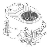
The inlet and exhaust valves are distinguished by the
mark (30) on the valve head and the head diameter.
Factory installed inlet and exhaust valves are different. If
a used valve is being installed, check whether it is an inlet
or an exhaust valve. Only the exhaust valve is available as
a replacement part – it can be used as either an inlet or
exhaust valve.
– Marking Valve diameter 38 mm, 40 mm
Standard part: Inlet “G”, Exhaust “H”
Replacement part: “H”
– Marking Valve diameter 43 mm
Standard part: Inlet “L”, Exhaust “M”
Replacement part: “M”
N Insert valve (13) in bore in cylinder and hold it in
position.
N Fit the spring retainer (1) and valve spring (2) on the
valve stem, press the spring retainer down and move
it sideways until the valve stem is in the small hole.
N Install the crankshaft, @ 16.9
N Install rocker arm and pushrod, @ 15.2.
Removing cam followers, cam gear
N Remove the shroud, @ 4.2.
N Remove the rewind starter, @ 5.2.
N Removing rocker arm, pushrod, @ 15.2.
N Pull boot off the spark plug.
N Unscrew the spark plug.
N Fit the locking screw 4282 890 2700 (25) in the spark
plug hole.
N Turn the crankshaft counterclockwise until the piston
butts against the locking screw (25).
N Unscrew the nut (10) and remove it together with the
starter cup (11).
N Take out the screws (9).
N Pry off the cover (8) at the recesses.
N Pull out the pin (6).
N Remove the cam followers (4, 5).
N Remove the cam gear (7).
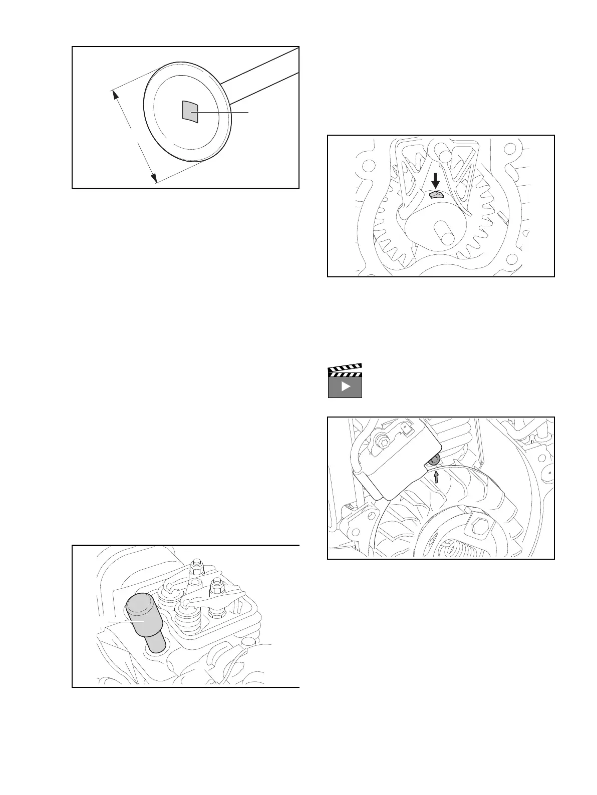
N Checking decompression system valve lifter:
Valve lifter (arrow) must project about 2 mm from the cam.
When the valve lifter is pressed counterclockwise, it must
move freely and retract fully.
Installing cam followers, cam gear, adjusting valve timing
N Rotate the crankshaft until the arrow on the front of
the flywheel is in line with the right-hand screw on the
ignition module (top dead center).
30
d
0000-GXX-2360-A0
Interactive video "Assembling the Valve Gear"
0000-GXX-1950-A00000-GXX-1939-A0

 Loading...