Series 4180 Powerhead 31
12.1 Special Servicing Tools, Servicing Aids
– Socket, T27 – 0812 542 2104
– Torque wrench – 5910 890 0302
– Screwdriver, T20 – 5910 890 2301
– Screwdriver, T27x200 – 5910 890 2415
– Punch-down tool – 5910 890 4000
– STIHL multipurpose grease – 0781 120 1110
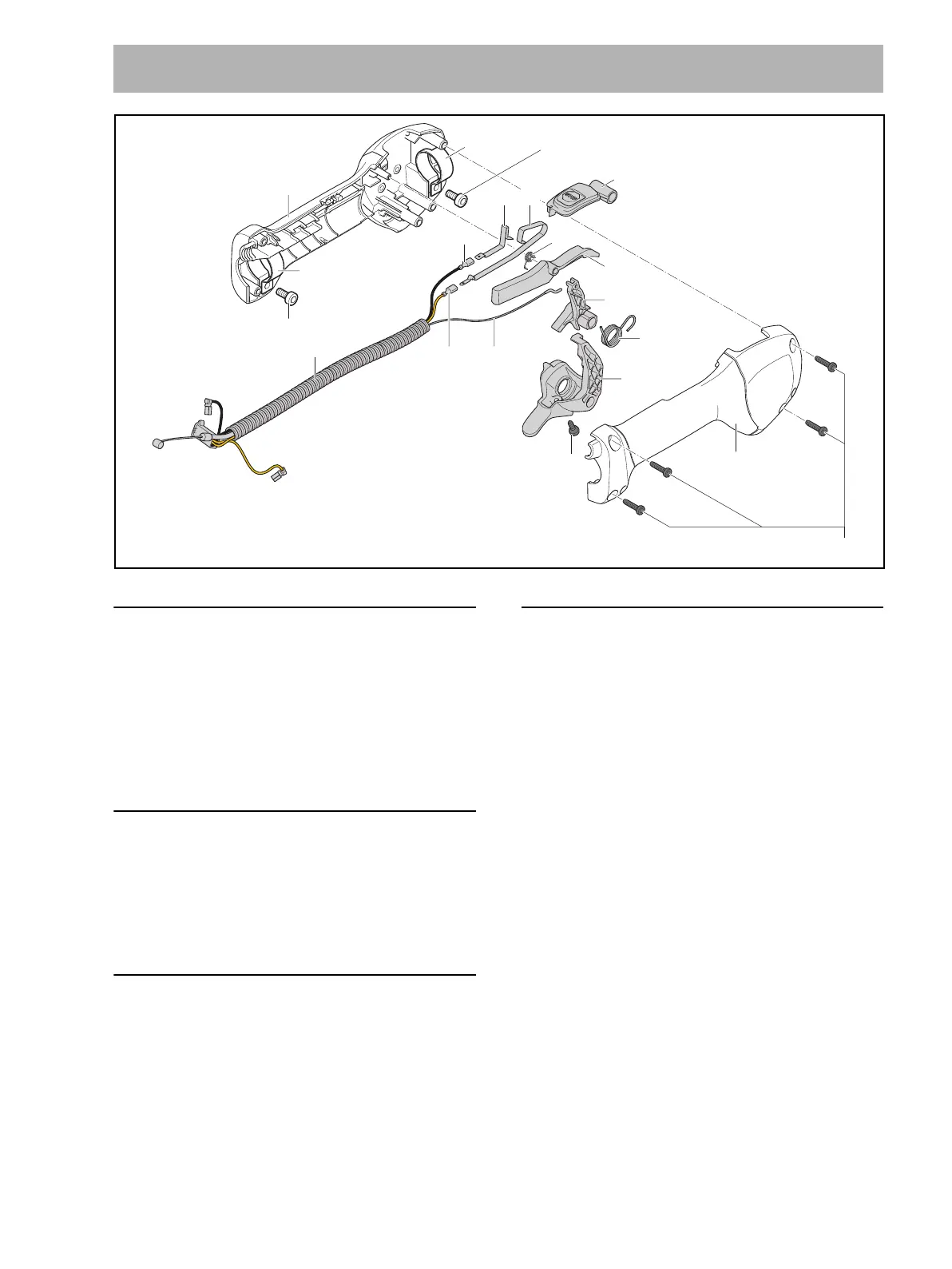
12.2 Removing the Control Handle
N Remove the drive tube.
N Loosen the screws (3) and pull the control handle off
the tube.
N Remove short-circuit wire, ground wire and throttle
cable from the engine, @ 8.8.
12.3 Fitting the Control Handle
N Fit ground wire, short-circuit wire and throttle cable on
the engine, @ 8.11.
N Slide the control handle onto the tube so that lever (6)
faces up.
N Insert and tighten down the screws (3).
N Push the protective hose into the retainer so that it
remains straight.
12.4 Disassembling the Control Handle
N Remove the control handle, @ 12.2.
N Take out the screws (12).
N Remove ‘outer handle molding’ (18).
N Relieve tension of torsion spring (10).
N Remove the throttle trigger (11) together with
lever (9) and torsion spring (10).
N Unhook the throttle cable (14).
N Take lever (9) with torsion spring (10) out of the
throttle trigger (11).
N Remove the torsion spring (10).
N Remove the lockout lever (8).
N Remove the torsion spring (7).
N Inspect the lockout lever (8), torsion springs (7, 10)
and throttle trigger (11), and replace if necessary.
12 Control Handle – Loop Handle
2
10
11
9
8
2
6
7
13
1
16
54
17
3 M5x12 (5 Nm / 44 lbf. in.)
M5x12 (5 Nm / 44 lbf. in.)
3
P4x16 (1,3 Nm / 12 lbf. in.) 12
14
18
15
0000-GXX-2324-A0

 Loading...