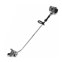
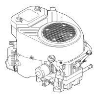
Series 4180 Powerhead16
N Insert extension 4180 893 4400 (11), small diameter
first, in the square hole in the clutch drum (1).
N Apply puller 5910 890 4400 (1) with jaws (profile No.
9) so that the jaws engage the recesses in the clamp
(6).
N Pull clamp (6) with rubber element (5) out of the fan
housing (3).
N If necessary, replace the clamp (6) or rubber element
(5).
7.5 Installing the Rubber Element
N Coat the rubber element (5) with OH 723 press fluid.
N Push the rubber element (5) onto the clamp.
N Use installing sleeve 4119 893 2400 to press the
rubber element (5) and clamp (6) into the fan housing
(3) as far as stop.
N Fit the screw (9) together with the washer (8).
N Fit the retaining ring (7).
N Install the fan housing (3), @ 7.3
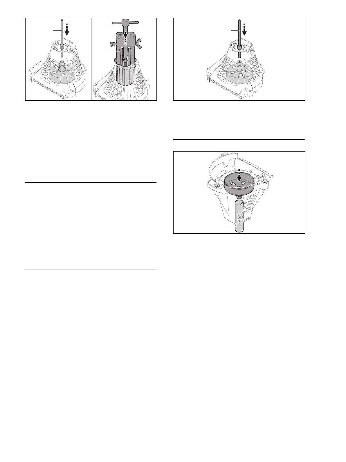
7.6 Removing the Clutch Drum
The ball bearing in the fan housing cannot be removed or
replaced. If the ball bearing is worn, a new fan housing
with built-in ball bearing must be installed.
N Remove the fan housing (3), @ 7.1.
N Remove the retaining ring (2) with A10 flat pliers –
0816 610 1495.
N Use ring 5910 893 7005 to support the fan housing
(3) so that it is upright.
N Insert extension 4180 893 4400 (11), small diameter
first, in the square hole in the clutch drum (1).
N Use press to remove the clutch drum (1).
7.7 Installing the Clutch Drum
N Remove rubber element, @ 7.1
N Use sleeve 1120 893 2400 (12) to support inner race
of ball bearing in the fan housing (3).
N Heat inner race of ball bearing in fan housing (3).
N Fit the clutch drum (1) in the ball bearing.
N Press home the clutch drum (1) as far as stop.
N Install new retaining ring (2) with A10 flat pliers –
0816 610 1495.
N Install the rubber element, @ 7.1
N Install the fan housing (3), @ 7.3
1
11
0000-GXX-1934-A0
11
0000-GXX-1932-A00000-GXX-1933-A0
12
 Loading...