BT 131 17
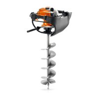
N Take out the screw (13).
N Pry out the insert (14).
N Pry the brake band (15) out of its seat (arrow).
Do not overstretch the brake band (15).
N Disengage the auger brake.
N Unhook the brake band (15) from the lever (9).
N Check brake band (15) for wear, @ 11.4.
11.4 Checking Brake Band for Wear
Install a new brake band if one of the following points
applies:
– Large areas of wear on inside.
– Partially worn areas on outside.
– Thickness of brake band less than 0.9 mm / 0.035 in
at any point.
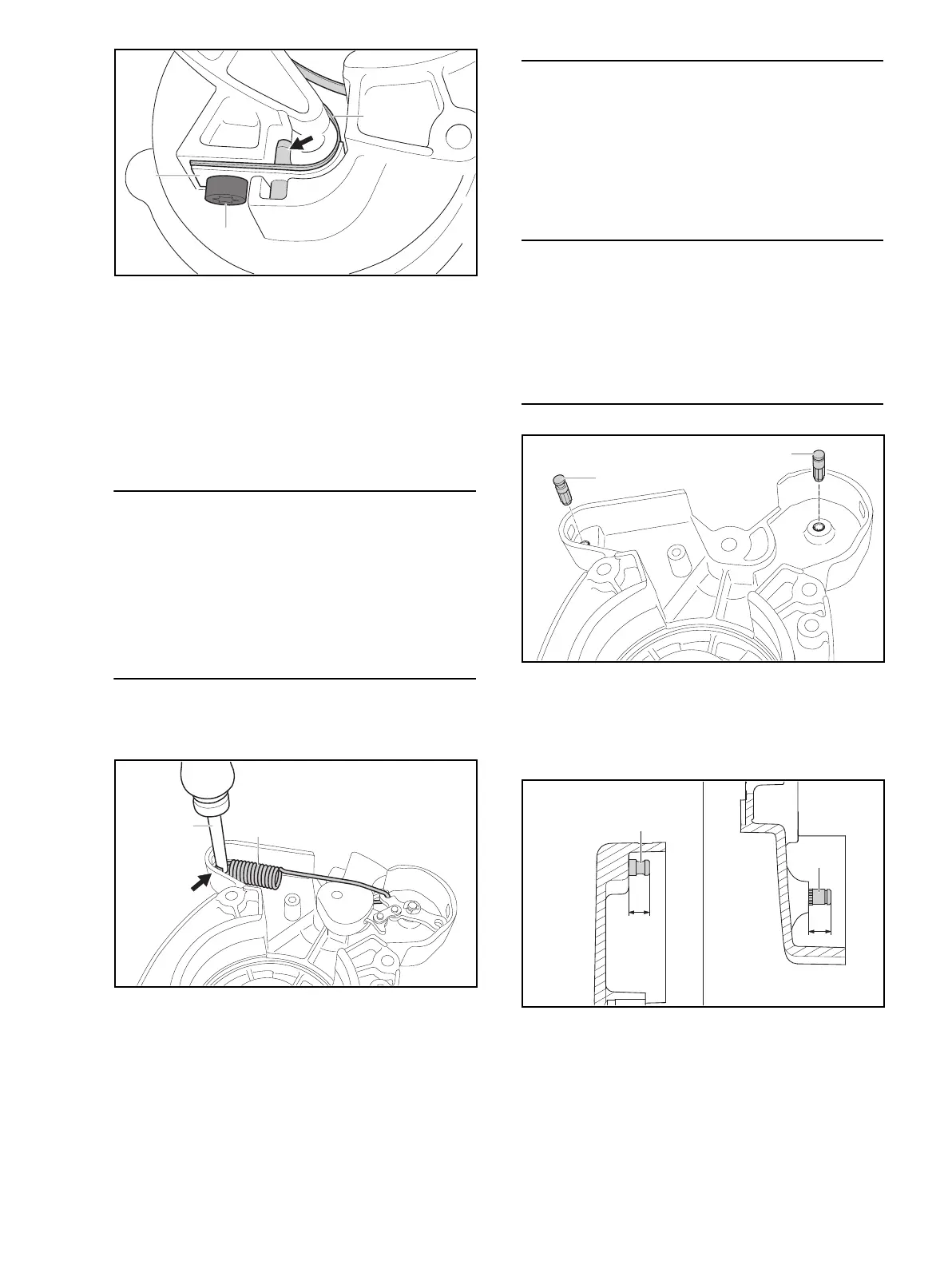
11.5 Removing the Brake Lever
N Remove the brake band, @ 11.3.
N Engage the auger brake.
N Use assembly tool 1117 890 0900 (19) to unhook
brake spring (16) from anchor pin (17, arrow).
N Unscrew the bearing pin (1).
N Remove the E-clip (10).
N Push out the retainer (2).
N Pull out the brake lever (9).
11.6 Removing the Flat Springs
N Remove the brake lever, @ 11.5.
N Take out the screw (3).
N Remove the hooked flat spring (4).
N Remove the two flat spring (5).
N Take out the nut (6).
11.7 Removing the Pins
N Remove the flat springs, @ 11.6.
N Use 3 mm (1/8 in) diameter pin punch to drive out pin
(8) from the outside.
N Use 3 mm (1/17 in) diameter pin punch to drive out
pin (8) from the outside.
11.8 Installing the Pins
N Coat knurled portion of new pins (8 and 17) with
Loctite 242.
N Insert the pins (8 and 17) in the bores so that their
knurling meshes with the knurling in the clutch
housing (7).
N Drive pin (17) home until height
‘a’ is about 5.5 - 5.7 mm (about 0.22 in).
N Drive pin (8) home until height ‘b’ is
about 6.0 - 6.2 mm (about 0.24 in).
N Install the flat springs, @ 11.10.
15
14
13
0000-GXX-2681-A0
19 16
0000-GXX-2714-A0
8
17
0000-GXX-2715-A0
8
17
a
b
0000-GXX-2716-A0
 Loading...