24 Series 4144 Components FC, FS, KM
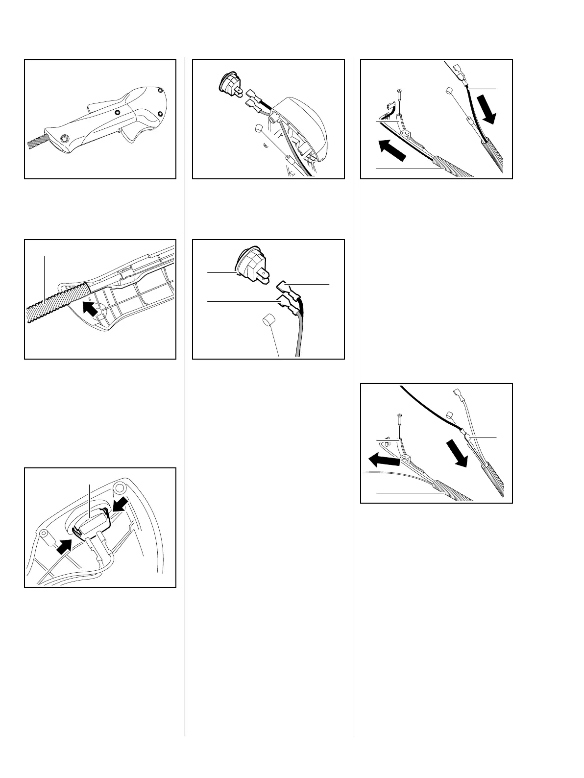
– Remove the handle molding and
levers, b 7.4
: Pull the protective tube (1) out of
its seat (arrow) in the handle
molding.
– Pull the wires and throttle cable
out of the guides.
: Squeeze the retaining tabs
(arrows) together and push the
stop switch (1) out of the handle
molding.
– Pull the stop switch (1) with wires
out of the handle molding.
545RA078 TG
545RA079 TG
1
545RA080 TG
1
: Disconnect the wires from the
stop switch.
– Check the short circuit wire (1),
ground wire (2) and stop switch
(3), and replace if necessary.
A faulty ground wire may impair or
prevent operation of the short circuit
wire. The ground wire must
therefore be tested for good contact
and continuity.
– Check operation of the stop
switch and replace it if necessary.
545RA081 TG545RA082 TG
3
1
2
– Tie a thin piece of string to the
straight terminal on the short
circuit wire (1).
: Pull short circuit wire (1) out of
the protective tube (2) in direction
of throttle cable retainer (3) and
undo the string.
– Check the short circuit wire and
replace if necessary.
– Check the throttle cable and
replace if necessary, b 8.6.1
– Tie the thin piece of string to the
straight terminal of the new short
circuit wire (1).
: Starting at the throttle cable
retainer (3), pull the short circuit
wire (1) through the protective
tube (2) and undo the string.
The same method can be used to
remove and install the ground wire
and throttle cable in the protective
tube.
545RA083 TG
2
1
3
545RA084 TG
2
1
3
 Loading...