25Series 4144 Components FC, FS, KM
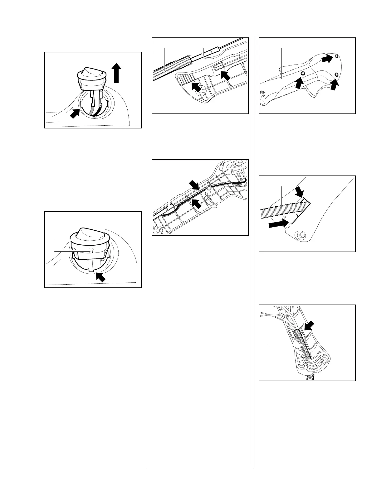
Installing
– Thread the short circuit and
ground wires through the hole
(arrow) in the handle molding.
: Push the straight terminals of the
ground and short circuit wires
firmly onto the stop switch
connector tags.
: Position the stop switch (1) so
that the lug (2) engages the slot
(arrow) in the opening.
545RA085 TG545RA086 TG
1
2
: Push the protective tube (1) and
throttle cable (2) into their seats
(arrows) in the handle molding.
: Fit the wires, ground wire first, in
the guide (arrows) – position the
wires next to one another without
loops.
The throttle cable sleeve (1) must
locate in its seat in the handle
molding (2).
– Install the control levers, b 7.4
– Install the throttle cable in the
control handle, b 8.6.1
545RA088 TG
1 2
545RA089 TG
2
1
– Fit the handle molding (1) in
position.
: Insert screws (arrows) and
tighten them down firmly.
: Push the protective tube (1) with
wires and throttle cable into the
engine housing through the
opening (arrow).
: Press the protective tube (1) into
its seat (arrow).
545RA090 TG
1
545RA091 TG
1
545RA076 TG
1
 Loading...