•
Pinch hook of leg spring into
centre of lead approx. 5 mm
from end of lead.
•
Pull lead back into terminal so
that leg spring is properly located
inside it.
Important! Check that the separa-
te connecting nut is securely loca-
ted on the screw thread of spark
plugs with separate nut and
tighten the nut if necessary.
- Fit spark plug terminal on spark
plug.
- Refit shroud.
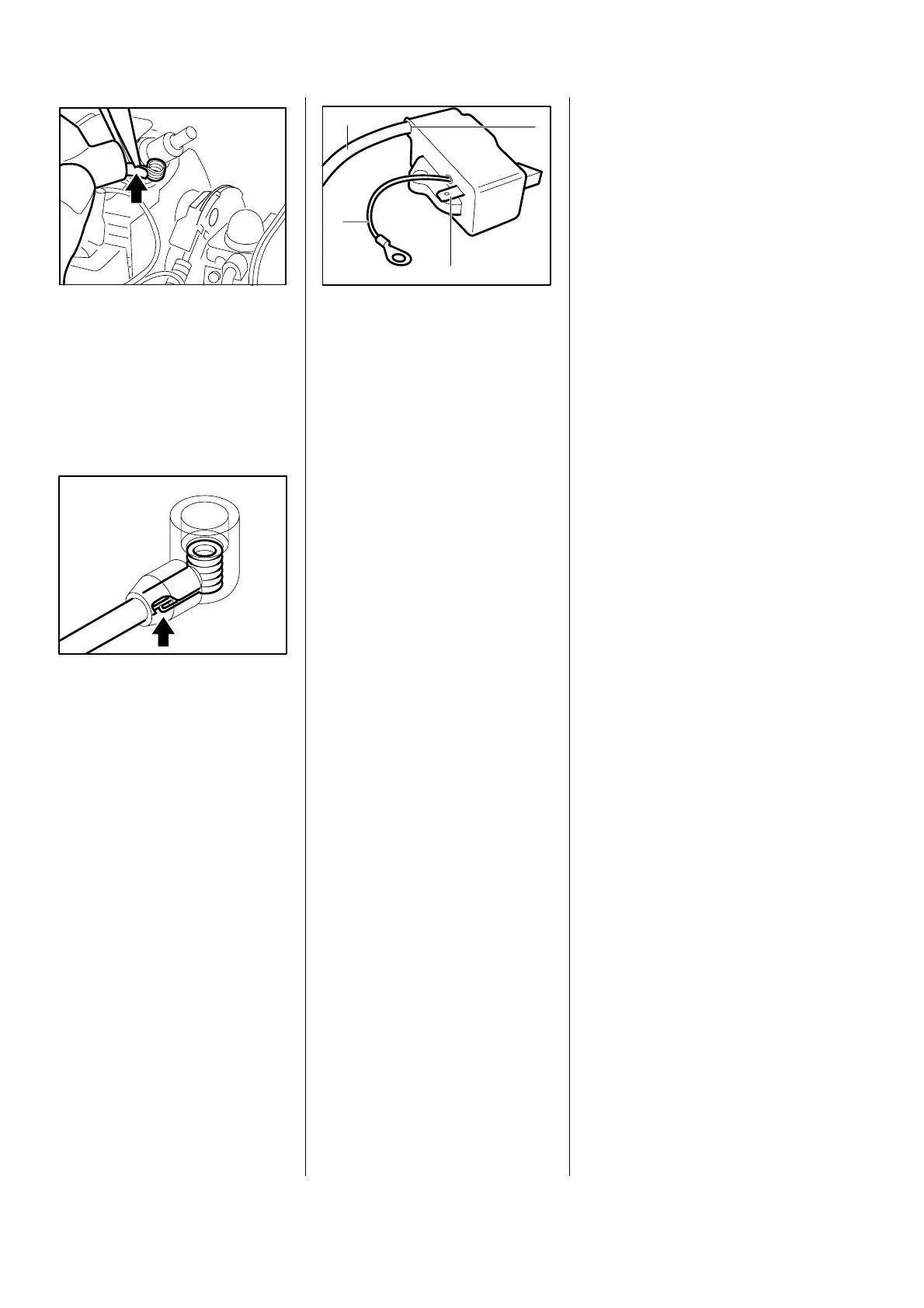
The ignition module accommoda-
tes all the components required to
control the ignition timing. Only
three electrical connections emer-
ge from the coil body:
1. High-voltage output (1) with
ignition lesd (2)
2. Connector tag (3) for short-
circuit wire
3. Ground lead (4)
Accurate testing of the ignition
module is only possible with test
equipment. Only a spark test
should therefore be carried out in
the workshop. The complete igni-
tion module must be replaced if an
ignition spark is not obtained
(although wiring and stop switch
are intact).
The ignition timing is fixed and
cannot be adjusted.
Since there is no mechanical wear
in these systems, the ignition
timing cannot become maladju-
sted. An internal fault in the circuit
can, however, alter the switching
point in such a way that a spark
test will still show the system to be
in order although timing is outside
the permissible tolerance. This
will impair engine starting and run-
ning behaviour.
366RA104 VA
392RA060
2
1
3
4
VA
392RA056
VA
5.2 Ignition module 5.2.1 Ignition timing
24
 Loading...