DocID030906 Rev 2 17/78
UM2271 Hardware layout and configuration
77
10.3.1 Drivers
Before connecting the 32L4R9IDISCOVERY to a Windows (7, 8, 10) PC via USB, a driver
for ST-LINK/V2-1 must be installed. It is available on the www.st.com website.
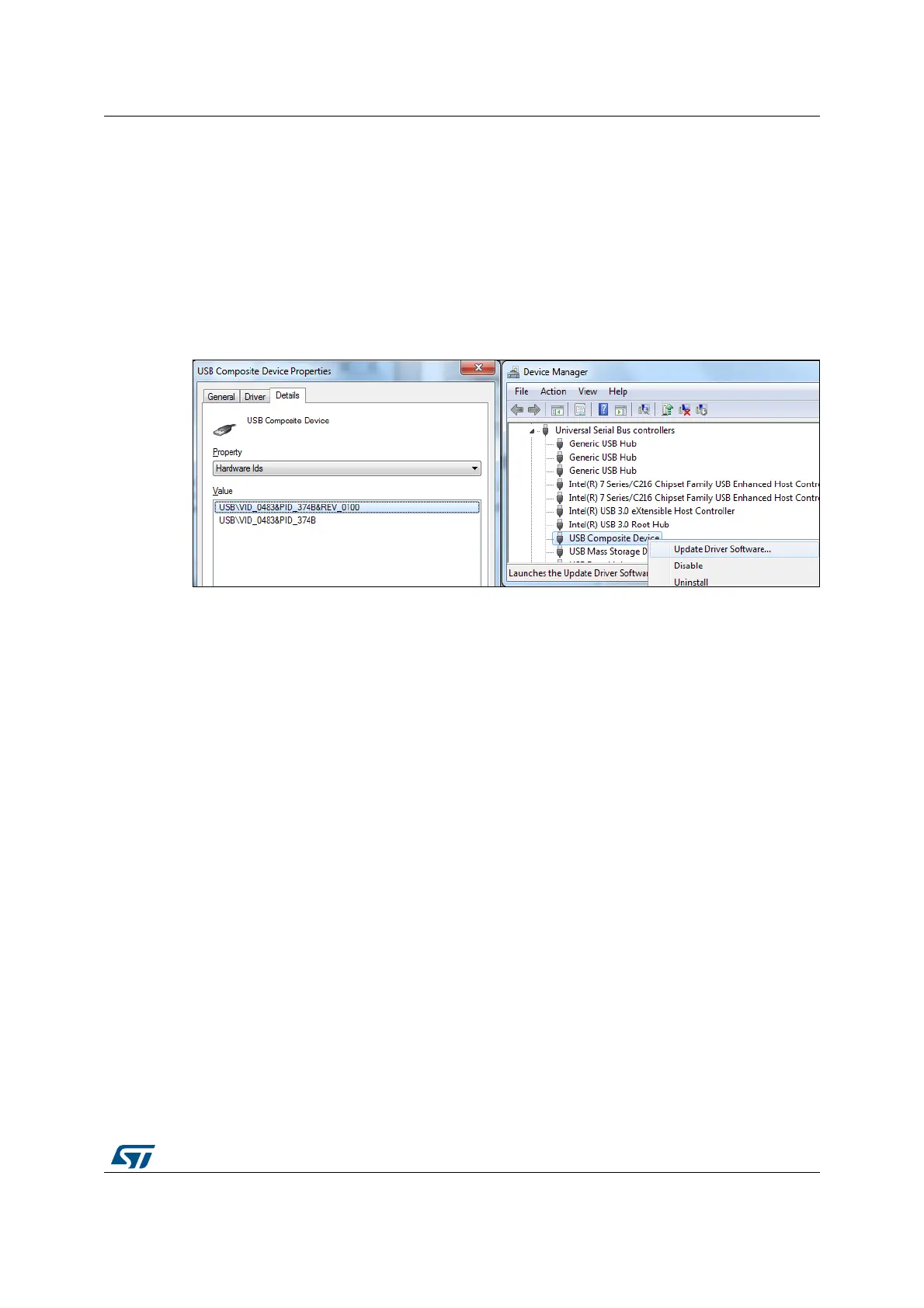
If 32L4R9IDISCOVERY is connected to the PC before the driver is installed, some
interfaces of the board may be declared as ‘Unknown’ in the PC device manager. In this
case the user must install the driver files, and update the driver of the connected device
from the device manager as shown on
Figure 8: How to update driver software
Note: Prefer using the ‘USB Composite Device’ handle for a full recovery.
Figure 8. How to update driver software
10.3.2 ST-LINK/V2-1 firmware upgrade
The ST-LINK/V2-1 embeds a firmware upgrade mechanism for in-situ upgrade through the
USB port. As the firmware may evolve during the life time of the ST-LINK/V2-1 product
(such as new functionality, bug fixes or support for new microcontroller families), it is
recommended to visit www.st.com before starting to use the 32L4R9IDISCOVERY and
periodically, in order to stay up-to-date with the latest firmware version.
10.4 Low-power consumption status
There is a way to make the board get into very low power consumption status in which the
current on +5
V can be below 20 uA. How to get into the low power mode:
1. The connections between ST-LINK/V2-1 and MCU must be disconnected by micro
switch SW1 manually (see
Table 3 below). Set JP4 on (7) ARD position, and put JP5 in
ARD-5V IN position. Remove JP10. Then, connect an external 5 V power supply on
CN16 pin 5 5V and on GND.
2. Peripherals (including display, CTP and PSRAM) are powered off by MOSFET which is
controlled by MFX_GPIO8 / MFX_aGPIO2 (put them as input floating), and by setting