DocID030906 Rev 2 37/78
UM2271 Connectors
77
Please, take care that this connector shares many GPIOs with other functions on the Board:
for more detailed information please refer to
Appendix A: GPIO assignment and sharing.
In addition, to have a quick look at STMod+ GPIO sharing and multiplexing, and to get a
quick view on other Alternate functions available on its pins, please refer to
Appendix C:
STMod+ GPIO sharing and multiplexing.
Note: Limitation: The STMod+ interface is not compatible with JP7 setting at +1V8.
Note: Limitation: if STMod+ pin 17 is used, please take care to disconnect SB1 first. If STMod+ pin
18/20 is used, please activate MIC_VDD GPIO (PH2) at high level first.
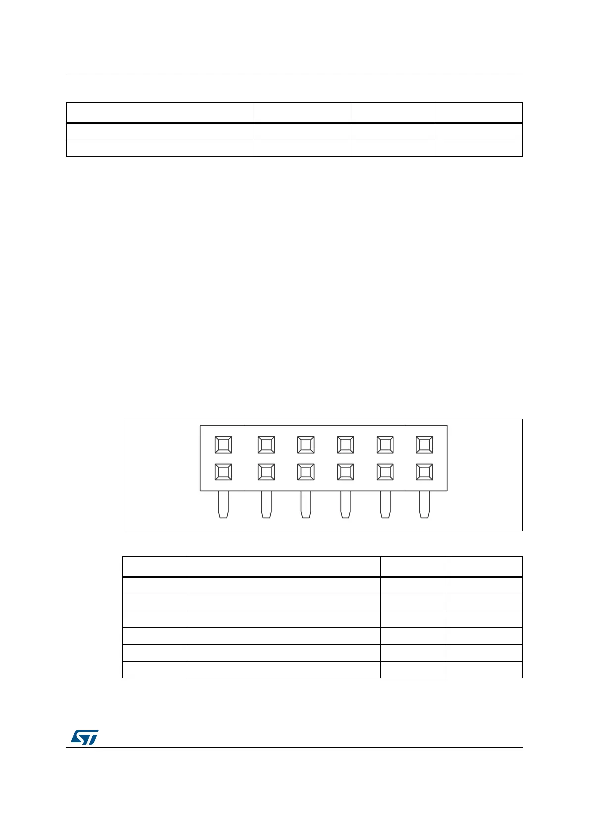
11.7 PMOD connector CN3
The standard 12-pin PMOD connector is available on STM32L4R9I-DISCO Discovery board
to support low frequency, low I/O pin count peripheral modules. The PMOD interface which
has been implemented on STM32L4R9I-DISCO Discovery board is compatible with the
PMOD type 2A & 4A I/O signal assignment convention.
Figure 15. PMOD connector CN3
STMod+ pin 3 SPI2_MISOp USART3_RX USART3_RX
STMod+ pin 4 SPI2_SCK SPI2_SCK USART3_RTS
1. UART / SPI defines default configuration for STMOD+_SEL_0 and STMOD+_SEL_1.
Table 20. Quad SPDT switch configuration (continued)
Pin number SPI UART / SPI
(1)
UART
Table 21. PMOD connector CN3
Pin number Description Pin number Description
1 SPI2_CS/USART3_CTS (PA6) 7 INT (PC6)
2 SPI2_MOSIp/USART3_TXD (PB15/PB10) 8 RESET (PI7)
3 SPI2_MISOp/USART3_RXD (PB14/PB11) 9 NA
4 SPI2_SCK/USART3_RTS (PB13/PA15) 10 NA
5GND 11GND
63V3 123V3
06Y9
)URQWYLHZ