STMod+ GPIO sharing and multiplexing UM2271
52/78 DocID030906 Rev 2
Appendix C STMod+ GPIO sharing and multiplexing
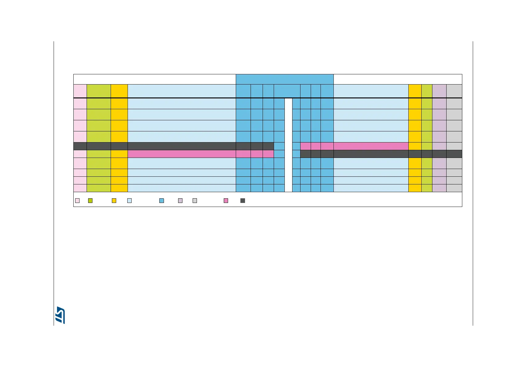
Table 31. STMod+ GPIO sharing and multiplexing
Shared or exclusive functions STMod+
(1)
Shared or exclusive functions
DSI ARD PMOD Some other Alternate Functions
(2)
Basic SB
(3)
Port Pins Port SB Basic Some other Alternate Functions
(2)
PMOD ARD CAM
Dig
Mic
- -
CTSS3 /
CSN2
LCTS1 / T3.1 / T16.1 / [OP2_I+ / AD1.11]
CTSS3 /
CSN2
- PA6 1
-
11 PC6 - INT SA2.MCKA / DF1.C3 / T3.1 / T8.1 INT - D0 -
TXS3
MOSI2
MOSI2/T15.2
TXS3
MOSI2
LRX1 / T2.3 / SCL2 / SCL4 / DF1.D7 / [CP1_O]
DF1.C2 / T1.3N / T8.3N / T15.2 / SA2.SDA / RTC_RFIN
TXS3
MOSI2
20
21
PB10
PB15
2 12 PI7 - RST T8.3 RST - D7 -
DC/X MISO2
RXS3
MISO2
SDA2 / SDA4 / LTX1 / DF1.C7 / T2.4 / [CP2.O]
SA2.MCKA / SDA2 / RTSS3 / DF1.D2 / T1.2N / T8.2N / T15.1
RXS3
MISO2
16
17
PB11
PB14
3 13 PA4 - ADC LT2.O / [AD1.9 / DAC1.1] - D7 HSYNC -
SCK2 SCK2
RTSS3
SCK2
SA2.FSB / RXS2 / RTS4 / T2.1 / T2.E
SCL2 / CTSS3 / LCTS1 / DF1.C1 / T1.1N / T15.1N / TXC2 / SA2.SCKA
RTSS3
SCK2
18
19
PA15
PB13
4 14 PA5 - PWM SCK1 / T2.1 / T8.1N / [AD1.10 / DAC1.2] - A5 - -
- - - - GND - GND 5 15 +5V - +5V - - - - -
- - - - +5V - +5V 6 16 GND - GND - - - - -
- SCL3 - DF1.CO / LTX1 SCL3 - PG7 7 17 PB12 - GPIO
NSS2 / SA2.FSA / SMBA2 / CKS3 / LRTS1 / RXC2 /
DF1.D1
- - - DF1.D1
- - - T8.E MOSI2 - PI3 8 18 PC2* - GPIO DF1.CO / MISO2 / LT1.2 / [AD1.3] - - - DF1.CO
- - - T8.4 MISO2 - PI2 9 19 PC7 - GPIO T3.2 / T8.2 / DF1.D3 - - D1 -
- SDA3 - LRX1 SDA3 - PG8 10 20 PC2* - GPIO same as pin 18 - - - DF1.CO
Legend:
= DSI = Arduino Uno = Pmod = Alternate Functions = STMod+ = CAM = Digital Microphone = Supply = GND
1. This Table 31 gives description of the signals available on the STMod+ connector
It also shows which signal is shared with other board connector or function
In some boards, Solder bridges (SB) are present to manually select which function is wired by default (but here, please refer to point (3) below)
Analog signals are in brackets [xxx]
The I2C bus on pins 7 / 10 might be shared with built-in discovery slave devices. Please check the slave address of your device when adding it to the bus.
2. RTSS3 stands for USART3_RTS
AD1.3 stands for ADC_1_IN3
T1.3N stands for TIM_1_CH3N
DAC1.1 stands for DAC_1_OUT1
MOSI2 stands for SPI2_MOSI
RST stands for RESET
INT stands for INTERRUPT
DF1.C3 stands for DFSM1_CKIN3
SDA3 stands for I2C3_SDA
LTX1 stands for LP_UART1TX
LT2.O stands for LPTIM2_OUT
NSS2 stands for SPI2_NSS
RXC1 stands for CAN_1_RX
SA2.SCKA stands for SAI2_SCLK_A
3. The solder bridges (SB) are available on PCB to select chosen Port, but they are not used by default: Instead of SB, an embedded SPDT quad switch is used to select Port. It is controlled by 2
GPIOs from the MFX_V3 Expander (STMOD+_SEL_0 and _1), please see Table 32 description below (Bold text is default configuration to support MikroBUS modules using MB1280 fan-out board)