Connectors UM2271
36/78 DocID030906 Rev 2
please refer to ST Fanout board user manual and to relevant datasheets of associated
modules.
For details about STMod+ interface, please refer to STMod+ connector interface
specification.
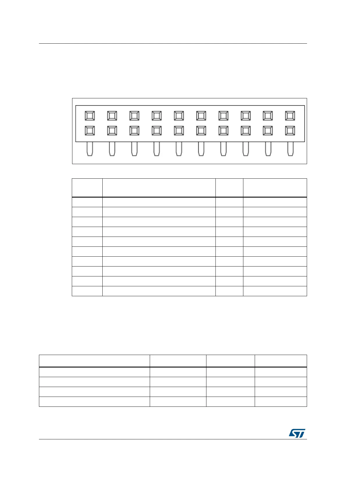
Figure 14. STMod+ connector CN1
In order to be able to support selection of SPI or UART functions connection on STMod+ by
software, a quad SPDT switch has been added. It is controlled by two GPIOs from MFX
circuit and enables MCU signal selection for pins 2, 3 and 4. By default, STMod+ connector
is selected, and STMOD+_SEL_0 and STMOD+_SEL_1 of MFX circuit are set to support
one of the STMod+ interface configuration.
Table 19. STMod+ connector CN1
Pin
number
Description
Pin
number
Description
1 SPI2_CS/USART3_CTS (PA6) 11 INT (PC6)
2 SPI2_MOSIp/USART3_TXD (PB15/PB10) 12 RST (PI7)
3 SPI2_MISOp/USART3_RXD (PB14/PB11) 13 ADC (PA4)
4 SPI2_SCK/USART3_RTS (PB13/PA15) 14 PWM (PA5)
5GND15+5V
6 +5V 16 GND
7 I2C3_SCL (PG7) 17 GPIO (PB12)
8 SPI2_MOSIs (PI3) 18 GPIO (PC2)
9 SPI2_MISOs (PI2) 19 GPIO (PC7)
10 I2C3_SDA (PG8) 20 GPIO (PC2)
06Y9
)URQWYLHZ
Table 20. Quad SPDT switch configuration
Pin number SPI UART / SPI
(1)
UART
STMOD+_SEL_0 (GPIO6 of MFX_V3) 0 1 1
STMOD+_SEL_1 (GPIO7 of MFX_V3) 0 0 1
STMod+ pin 1 (directly connected to PA6) SPI_CS SPI_CS USART3_CTS
STMod+ pin 2 SPI2_MOSIp USART3_TX USART3_TX