Fanout board (MB1280) UM2271
72/78 DocID030906 Rev 2
The mikroBUS pinout assignment is available at the: http://mikroe.com website.
E.2 ESP-01 Wi-Fi
®
board compatible connector
The ESP-01 Wi-Fi board connector is 2.54 mm pitch with 2x4-pin female connectors.
Table 34 shows the definition of the pins.
E.3 Compatible connectors for the Grove boards
The two connectors of the Grove board are 2.54 pitch with 1x4-pin male connectors, the
part number is 1125S-SMT-4P.
E.3.1 Compatible connector for I2C Grove boards (Fanout CN3)
The CN3 connector is compatible with Grove- Barometer sensor (BMP180) and Grove-LCD
RGB Backlight boards using cable for connection.
Table 35 shows the definition of the pins.
Table 33. Description of the mikroBUS connectors (CN11 and CN10)
(1)
1. Please refer to Appendix C to check STMod+ pin sharing with other functions of the 32L4R9IDISCOVERY
STMod+ connector
CN11 number
Function of
mikroBUS
Pin
number
Pin
number
Function of
mikroBUS
STMod+ connector
CN10 number
STMod+#13-ADC AN 1 1 PWM STMod+#14-PWM
STMod+#12-RST RST 2 2 INT STMod+#11-INT
STMod+#1-CS CS 3 3 RX STMod+#3-RX
STMod+#4-SCK SCK 4 4 TX STMod+#2-TX
STMod+#9-MISOs MISO 5 5 SCL STMod+#7-SCL
STMod+#8-MOSIs MOSI 6 6 SDA STMod+#10-SDA
- +3.3 V 7 7 +5 V STMod+#6#15 +5V
STMod+#5#16 GND GND 8 8 GND STMod+#5#16 GND
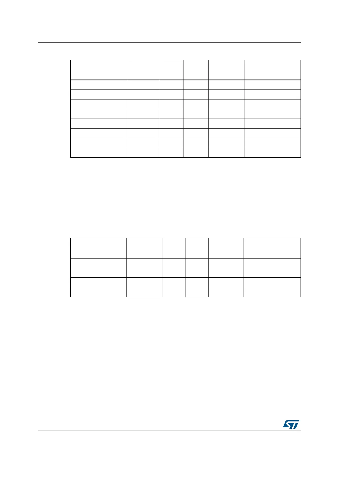
Table 34. Description of the ESP-01 Wi-Fi board connector pins
(1)
1. Please refer to Appendix C to check STMod+ pin sharing with other functions of the 32L4R9IDISCOVERY.
STMod+ connector
number
Function of
ESP-01
Pin
number
Pin
number
Function of
ESP-01
STMod+ connector
number
STMod+#5#16 GND GND 1 8 TXD STMod+#3-RX
STMod+#14 GPIO2 2 7 CH_PD STMod+#13
STMod+#11 GPIO0 3 6 RST STMod+#12-RST
STMod+#2-TX RXD 4 5 VCC -