DocID030906 Rev 2 27/78
UM2271 Hardware layout and configuration
77
Other LEDs are present on the 32L4R9IDISCOVERY. Find below a summary list of all
buttons and LEDs, with their description.
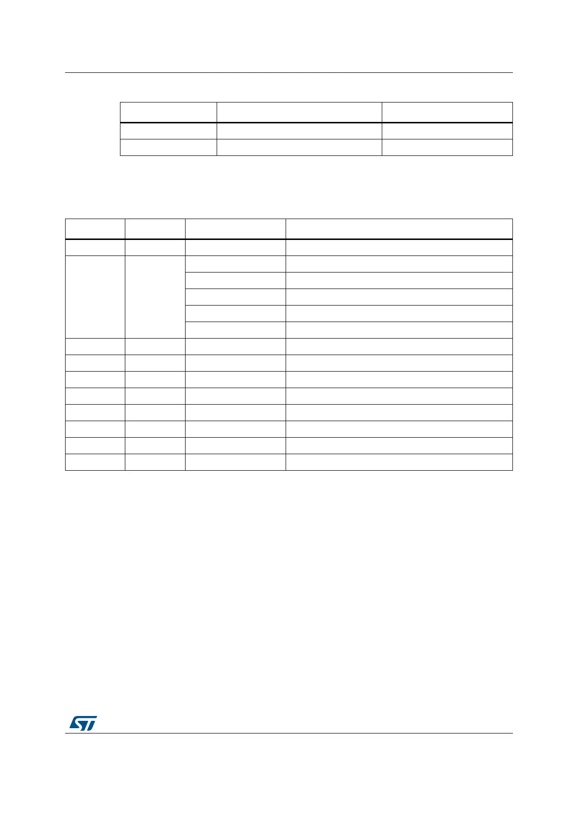
Table 11. LD1 and LD2 details
LED MCU port control color
LD1 PB0 (MFX_GPIO0 from MFX) Orange
LD2 PH4 (from main MCU) Green
Table 12. Buttons and LEDs
Reference Color Function Comment
B1 black RESET For MCU, OCTO-SPI Flash, MFX_V3, CAMERA
B2 blue
SELECT with Wake-up alternate function, PC13
UP MFX_GPIO1, PB1
DOWN MFX_GPIO2, PB2
RIGHT MFX_GPIO3, PB3
LEFT MFX_GPIO4, PB4
LD1 orange USER1 MFX_GPIO0, PB0
LD2 green USER2 PH4
LD3 green ARDUINO PB13
LD4 red/green ST-LINK COM Green during communication
LD5 red ST-LINK USB FAULT Current higher than 625 mA
LD6 green VBUS USB OTG FS Status also available on PA9
LD7 red USB OTG FS OVCR Overcurrent detection, also on MFX_GPIO14, PB14
LD8 green 5V POWER -