DocID030906 Rev 2 39/78
UM2271 Connectors
77
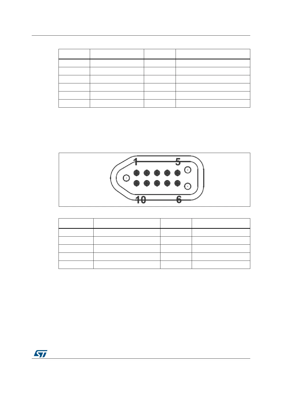
11.9 TAG connector CN8
The TAG connector footprint CN8 is used to connect STM32L4R9AI microcontroller for
programming or debugging the board.
Figure 17. TAG connector CN8
11.10 SWD header CN5
The 6-pin SWD header is used to program or debug an MCU in an external application
board using a dedicated cable connected to it. To use this SWD header interface, pins 2 and
3 of JP10 need to be connected with a jumper. Furthermore, SW1 must be set in OFF
position while R24 and R31 need to be disconnected.
By default, STLINK/V2-1 is used to program or debug on board MCU. Pin1 and 2 of JP10
are connected, SW1 is in ON position, R24 and R31 are connected.
10 DCMI_D6 (PB8) 25 DCMI_PWR_EN (MFX_GPIO12)
11 DCMI_D7 (PI7) 26 DCMI_NRST (NRST from MCU)
12 NC 27 I2C1_SDA (PG13)
13 NC 28 I2C1_SCL (PB6)
14 GND 29 GND
15 DCMI_PIXCK (PH5) 30 VDD
Table 22. Camera module connector CN2 (continued)
Pin number Description Pin number Description
Table 23. TAG connector CN8
Pin number Description Pin number Description
1 VDD 10 NRST (PH3, RESET#)
2 SWDIO (PA13) 9 NA
3GND 8NA
4 SWCLK (PA14) 7 NA
5GND 6SWO (PB3)