DocID030906 Rev 2 19/78
UM2271 Hardware layout and configuration
77
10.6 Power supply
10.6.1 Power supply sources
32L4R9IDISCOVERY is designed to be powered by +5 V DC power supply. It is possible to
configure the 32L4R9IDISCOVERY to use any of the sources listed in
Table 4.
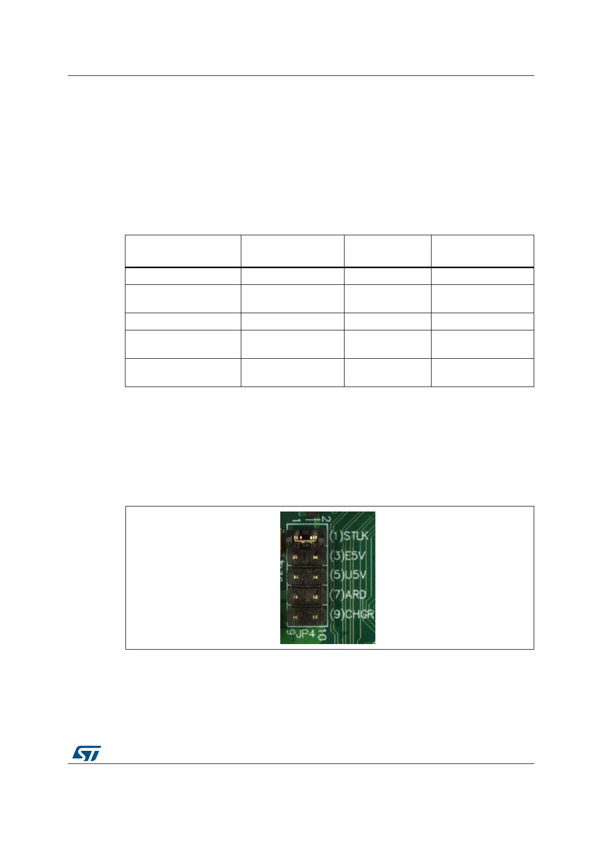
By default, the JP4 header must have a jumper on (1) STLK and SW1 is placed in ON
position. Any JP4 position different from (1) STLK requires SW1 to be placed in OFF
position (see
Table 3).
Note: 32L4R9IDISCOVERY must be powered by a power-supply unit or by an auxiliary equipment
complying with the standard EN-60950-1: 2006+A11/2009, and must be safety extra low
voltage (SELV) with limited power capability.
Figure 9 shows a physical description of the 10-pin header JP4 default configuration.
Figure 9. JP4 default configuration
Detailed description of all JP4 possible configurations are listed below and in Table 5:
• STLK: 5 V from the ST-LINK/V2-1 USB connector CN13 with 500 mA current limitation.
Power mechanism of supplying the board by STLINK/V2-1 is explained Section 10.6.3.
Table 4. 32L4R9IDISCOVERY power sources configuration
JP4 configuration
(function)
Power source
connector (pin name)
Voltage Available current
(1) STLK (USB_STLINK) CN5 (VBUS) 5 V 500 mA
(3) E5V (ARDUINO) CN16 (VIN) 6 V - 9 V => 5 V
Arduino Uno V3 shield
dependent
(5) U5V (USB_OTG_FS) CN8 (VBUS) 5 V 500 mA
(7) ARD (ARDUINO) CN16 (ARD-5V)
(1)
1. ARD-5V is a power output pin to Arduino connector CN16 (default) or a power input pin from Arduino
connector CN16, according to JP5 setting. See Table 6 below.
5 V
Arduino Uno V3 shield
dependent
(9) CHGR (USB_STLINK) CN5 (VBUS) 5 V
Power supply
dependent