Hardware layout and configuration UM2271
20/78 DocID030906 Rev 2
A jumper must be placed in location STLK of JP4, connecting pins 1 and 2. The green
LED LD8 is lit on to confirm presence of 5 V voltage.
• E5V: 5 V from the 6 V to 9 V DC from VIN pin of Arduino compatible connector CN16
(the U15 regulator is converting VIN into a 5 V voltage). The VIN input voltage is limited
to 9 V to keep temperature of the regulator U15 within its thermal safe area. A jumper
must be placed connecting pins 3 and 4 of JP4. The green LED LD8 is lit on to confirm
presence of 5 V voltage. SW1 must be placed in OFF position.
• U5V: 5 V from the 5 V DC of USB OTG FS user connector CN9. A jumper must be
placed in location USB of JP4, connecting pins 5 and 6.The green LED LD8 is lit on to
confirm presence of 5 V voltage. SW1 must be placed in OFF position.
• ARD: 5 V from the 5 V of Arduino compatible connector CN16. A jumper must be
placed in location ARD of JP4, connecting pins 7 and 8. The green LED LD8 is lit on to
confirm presence of 5 V voltage and at t the same time, pins 2 and 3 of JP5 must be
connected to get 5 V power from Arduino. SW1 must be placed in OFF position. In
case the main board provides 5 V to Arduino compatible connector CN16, which is the
default configuration, pins 1 and 2 of JP5 must be connected (see Table 6).
• CHGR: 5 V from 5 V DC power charger connected to USB STLINK (CN13). In this
case, if 32L4R9IDISCOVERY is powered by an external USB charger, then the debug
on CN13 is not available. When CHGR input is chosen, it is not recommended to
connect a PC on USB STLINK, because the 500 mA limitation is no more effective and
this may damage the PC. A jumper must be placed in location CHGR of JP4,
connecting pins 9 and 10. The green LED LD8 is lit on to confirm presence of 5 V
voltage. SW1 must be placed in OFF position.
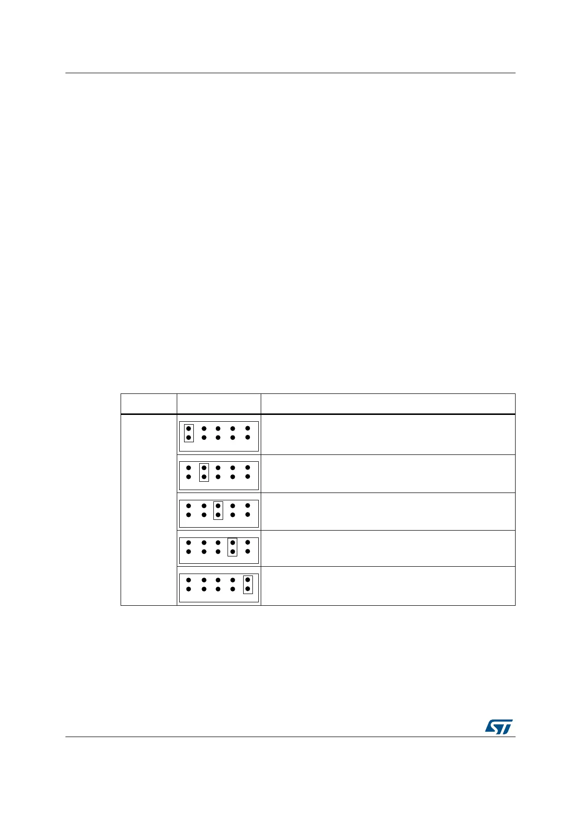
Table 5. JP4: power source selector setting
Jumper Setting Description
JP4
Default setting.
32L4R9IDISCOVERY is supplied though CN13 Micro-B
ST-LINK/V2-1 connector.
32L4R9IDISCOVERY is supplied though Arduino connector
CN16 (VIN).
32L4R9IDISCOVERY is supplied though USB OTG FS
connector CN9.
32L4R9IDISCOVERY powers ARDUINO or is supplied by
ARDUINO, according to JP5 setting in Table 6 below.
32L4R9IDISCOVERY is supplied though CN13 Micro-B ST-
LINK/V2-1 connector. In that case, the SB36 solder bridge must
be soldered.