217-8080
Talon SRX - User’s Guide
crosstheroadelectronics.com vexpro.com
Copyright 2017, Cross The Road Electronics, VEX Robotics Inc.
Updated: 2017-02-03
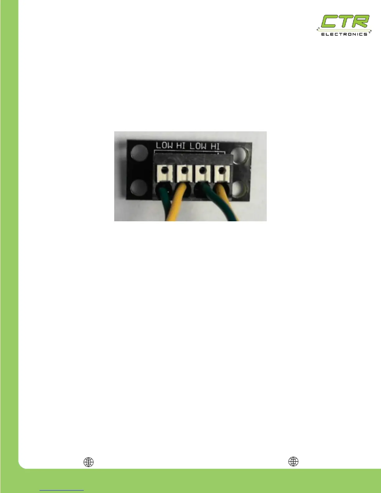
1.3.2.1. CAN Connector
The CAN Connector can be used to chain Talon SRX’s together without crimping connectors or
soldering. Each CAN Connector contains a four channel Weidmuller terminal block with two CAN
pairs (similar to other FRC CAN devices such as the Power Distribution Panel and Pneumatic Control
Module). The four holes can be used to provide strain relief to the CAN wires. Additionally the holes
can be used for mounting to the robot frame. Spacers or electrical tape may be used to prevent
shorting to the robot frame.
1.3.2.2. CAN Bus Wire Selection
Teams should consult the FRC game rules for CAN wiring requirements. However it is
recommended to use yellow for CANH and green for CANL for the following reasons…
Makes robot inspection and troubleshooting easier.
The colors match what is labeled on the FRC Robot Controller, Power Distribution Panel,
and Pneumatic Control Module.
The colors match the Talon SRX cable harness.
AWG 22 or similar gauge wiring can be used. An electric drill can be used to twist the CANH/CANL
wire pair.