217-8080
Talon SRX - User’s Guide
crosstheroadelectronics.com vexpro.com
Copyright 2017, Cross The Road Electronics, VEX Robotics Inc.
Updated: 2017-02-03
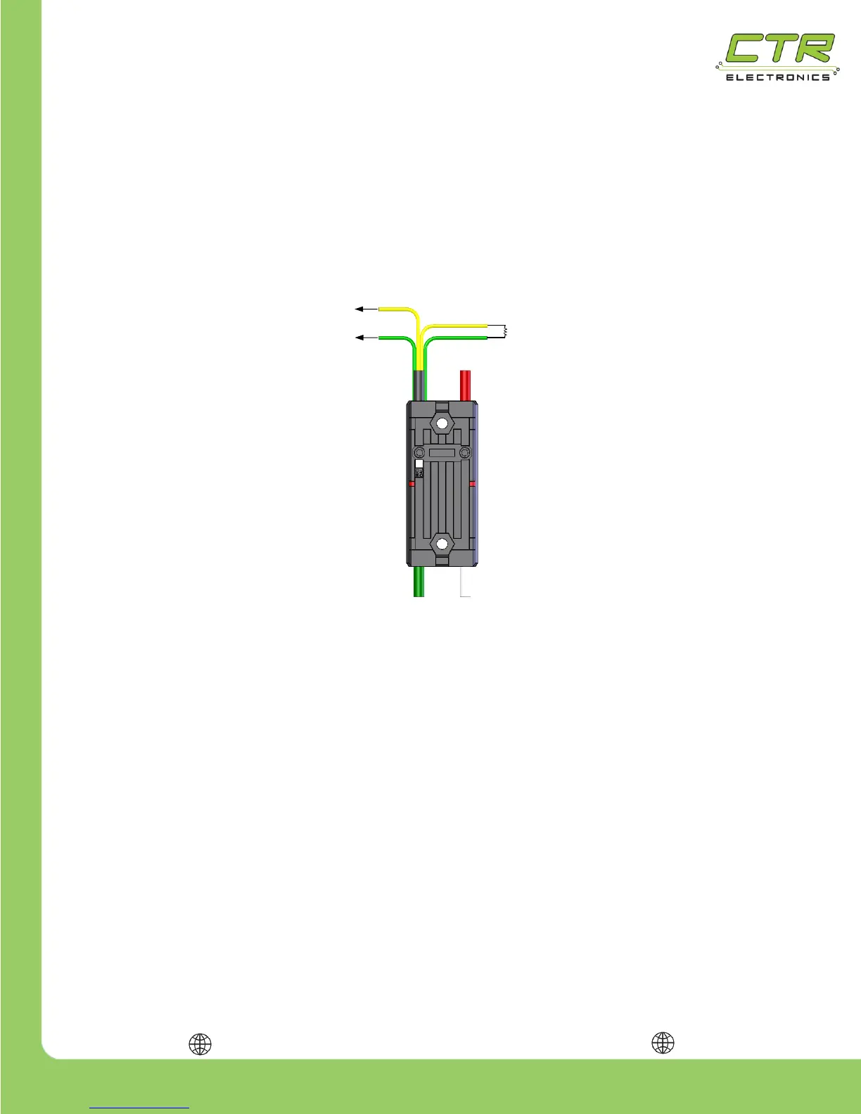
Another option is to explicitly ensure each Talon SRX has a unique ID assigned to it prior to wiring the
entire CAN bus harness. To do this, connect a yellow signal wire to the NI roboRIO CAN terminal
marked “H” and connect a green signal wire to the NI roboRIO CAN terminal marked “L” as shown in
the figure below. Connect the remaining green and yellow signal wires using a 120 Ω resistor as
shown in the figure below. Alternatively the Power Distribution Panel’s CAN interface can be wired
instead of a 120 Ω resistor since the PDP has an integrated resistor.
After the Talon SRX has been connected to the roboRIO, ensure there are no shorts, then apply
power and use the roboRIO Web-based Configuration page to assign the Talon SRX a unique ID.
TIP: Avoid using the default ID “0”, this makes adding new default Talons easier. The unique
ID is a 6-bit number; valid numbers are from 1 to 62. After the unique ID has been assigned, remove
power and repeat the process for each Talon SRX.
WARNING: When applying power to the Talon SRX for programming its unique ID, it may be
tempting to connect it directly to a 12V robot battery without a breaker – this is NOT recommended. If
the temporary power connectors short without a breaker protecting the wires, there is a high risk of an
electrical fire.