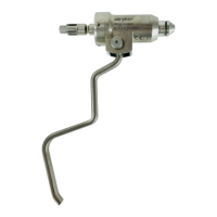
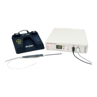
SERFAS consists of the RF Generator, Footswitch, Handpiece Cable and Probe. The RF Generator is a radio-frequency
energy-generating unit, designed to deliver a high frequency output to perform electrosurgical procedures. Components
of SERFAS, the Footswitch, Probe and Handpiece Cable are specifically designed to connect with the RF Generator
and are intended to be used together as a single unit. This system should only be used as indicated in this manual.
RF GENERARF GENERA
RF GENERARF GENERA
RF GENERA
TT
TT
T
OR OR
OR OR
OR
(REF - 278-100-000)
::
::
:
FRONT PANEL:
NOTE: Refer to Appendix B for front panel labeling definitions.
1. Mains Power Switch – The mains connection to the generator can be turned ON/OFF using this switch. The
switch will illuminate when mains power to the unit is turned on.
2. RF CUT output level change – Cut level UP and DOWN buttons will change the setting for energy delivered to the
tip during CUT mode. Output level selected should be as low as possible for the intended purpose and cannot be
changed while RF energy is being delivered. To scroll through levels, hold down either the UP or DOWN button until
desired level is reached.
3. CUT RF Output Level / Error Code Display – This display shows the set-point CUT level (1 through 10 depending
on probe used or ‘0’ during start-up display). In case of an error, the CUT RF Output Level display will show the
corresponding error code.
4. RF CUT Activation Indicator – A yellow indicator will illuminate when RF energy is delivered due to the CUT pedal/
button being pressed.
5. RF COAG output level set/change – COAG level setting will be controlled by three separate buttons (HIGH, MED,
and LOW) for high, medium and low settings, respectively. Pressing one of these options will set the corresponding
COAG level. Output level selected should be as low as possible for the intended purpose and cannot be changed
while RF energy is being delivered. The output level of HIGH, MED, and LOW settings depend on Probe type used.
Refer to the SERFAS Probe User Insert and Appendix A of this manual for COAG Level definitions.
6. RF COAG Activation Indicator – A blue indicator will illuminate when RF energy is delivered due to the COAG
pedal/button being pressed.
PRODUCT DESCRIPTION AND USE
1
6
3
410
8
9
11
2
75
12
4
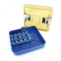
Pull-out Tray (see page 6)
 Loading...