Studer Innotec SA
RCC-02/-03
User manual V4.4.0 11
4
CONNECTION
The RCC-02 remote control must be firmly fastened using 3 screws on a flat support. The remote
control RCC-03 is meant to be integrated. It must be mounted by means of 4 screws (not supplied)
on a flat place without any mechanical constraints to the front plate. Once the RCC remote control
is fastened it can be connected to the inverter using the authorized cable only. If the cable is
damaged or if a socket is detached, the cable must not be connected since this can lead the whole
installation to malfunction.
A maximum of 3 remote controls can be connected to one unit.
4.1 SERIES CONNECTION
Devices in the Xtender series are equipped with a proprietary communication bus for data
exchange, configuration and updating of the system. Series connection is obtained by linking the
devices with the provided communication cables. This way a serial bus is created where the
terminations must be activated on the units on both ends.
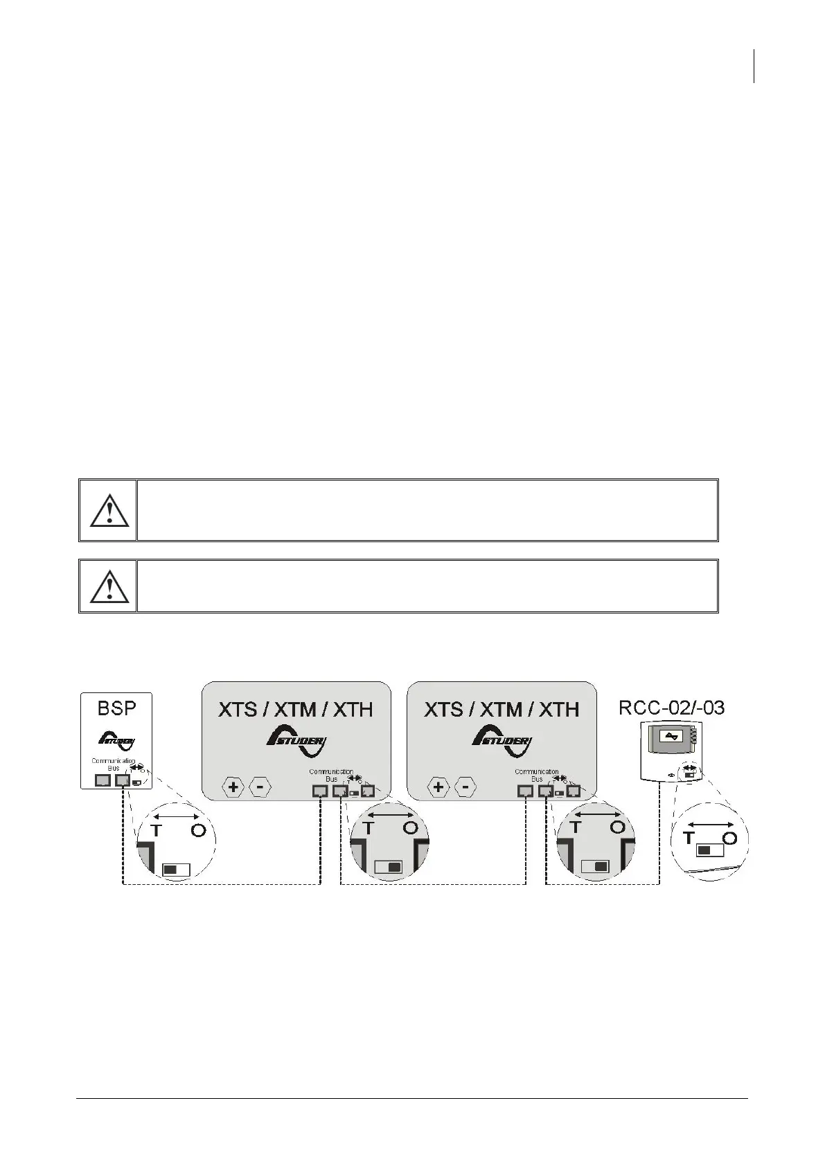
Each device is equipped with a switch offering to choose between open "O" and terminated "T". By
default all terminations are activated on each Studer Innotec product. The devices at the end of the
line must be set on "T" (one cable) and all the others on "O" (two cables).
A wrong setting of the terminations can lead to an erratic running of the
installation or impede its updating.
The remote control must never be placed in between two devices connected
to the battery (Xtender, VarioTrack, VarioString).
Exemple of an installation with indicated terminations.