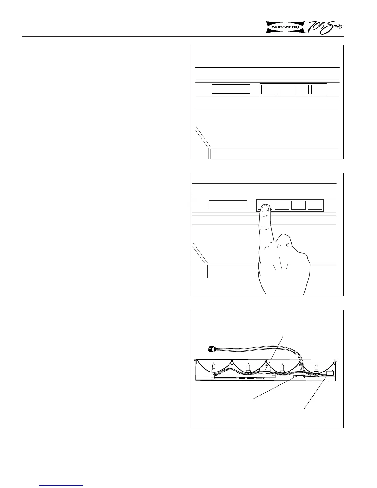
Figure 2-9. Control Panel Electrical Connections
ELECTRONIC CONTROL SYSTEM
The 700 Series electronic control system consists
of a control board and a display board. The con-
trol board includes the microprocessor relays, low
voltage transformers, electrical connections and an
alarm buzzer. The display board, which is part of
the control panel, includes an LCD (Liquid
Crystal Display), input buttons for setting controls,
and an alarm button. Below are instructions for
setting temperatures and for control panel removal.
NOTE: If the door is open for more than 15 sec-
onds the alarm will sound. The alarm can be dis-
abled by pushing the ALARM button (Figure 2-7).
The alarm will default to ON after a power out-
age.
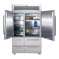
Temperature Settings
Normal operation of the display shows the temper-
ature of each zone (or compartment) at five second
intervals. The appropriate zone indicator lights up
when the corresponding temperature is displayed.
The following steps are necessary to adjust tem-
peratures.
1. Press ZONE key to show the temperature set
point for each zone (See Figure 2-8). Press the
zone key until the desired zone is flashing on
the LCD.
2. Press the WARMER or COLDER key to
achieve the desired temperature (Figure 2-8).
When setting is complete, wait for five seconds
and the control will return to normal operation.
NOTE: To adjust temperatures in next zone,
repeat steps 1 and 2 above.
Upper Control Panel Removal
Models 700TR, 700TC/I, 700TF/I
1. Remove the rear mounting screws at the back
of the light diffuser.
NOTE: Do not remove the light diffuser to access
the mounting screws. Look behind the diffuser
panel (Figure 2-7).
Models 700TR, 700TC/I, 700TF/I
Models 700TR, 700TC/I, 700TF/I
Models 700TR, 700TC/I, 700TF/I
Thermal cutout
Interlock switch
Door Sensor
 Loading...