COMPONENT INFORMATION
2-17
UNIT TRAY COMPARTMENT
The Unit Tray Compartment contains the unit tray
assembly, master power switch, icemaker solenoid
valve (700TFI, 700TCI, 700BFI only), 12 volt
transformer, and evaporator sump drain tube
heater.
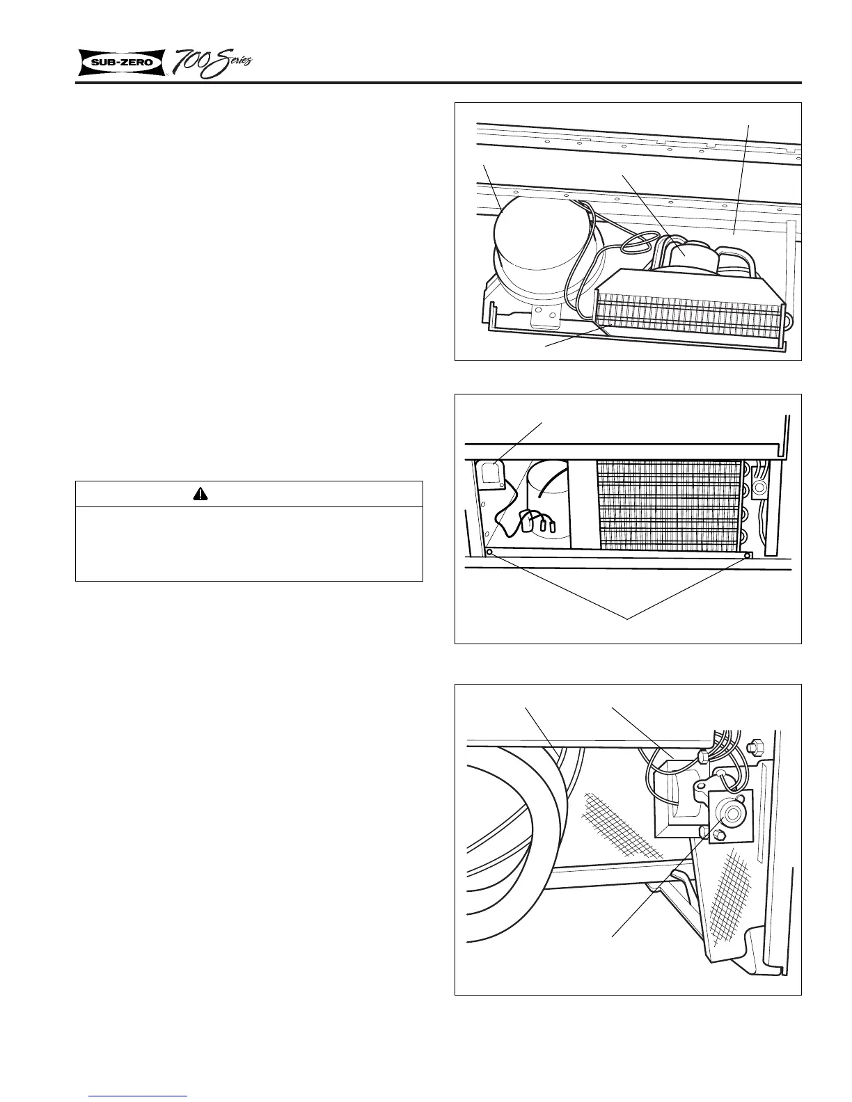
Unit Tray Assembly
The removable unit tray assembly was designed
for easy access to the compressor, condenser, con-
denser fan motor, and drain pan (Figure 2-27).
To remove the unit tray assembly, extract two
screws (Figure 2-28) that secure the tray to the
cabinet, located at the bottom left and right corner
of the cabinet. After the screws are removed, the
complete tray assembly can be slid forward to
expose the components.
Master Power Switch
The master power switch is located at the front left
of the unit tray compartment and is removed by
releasing the tabs at the back of the mounting
bracket, then unplugging (Figure 2-28).
NOTE: It is not necessary to slide the unit tray
assembly out to access the master power switch.
Icemaker Solenoid Valve
(700TFI, 700TCI, 700BFI Only)
The solenoid valve is located at the top right of the
unit compartment. To remove the solenoid valve,
extract the retaining screw and remove the sole-
noid retainer (Figure 2-29). After the retainer is
removed, slide the solenoid to the left. Then pull
forward slightly, unplug the electrical connectors
and disconnect the water line.
NOTE: It is not necessary to slide the unit tray
out to access the icemaker solenoid valve.
Figure 2-27. Unit Tray Assembly
Figure 2-28. Mounting Screws
Figure 2-29. Solenoid
CAUTION
When pulling the tray forward care must be
taken to not kink any tubing or rupture any
weld joints.
Drain pan
Fan motor
Compressor
Condenser
Mounting screws
Drain tube heater
12V Transformer
Solenoid valve
Master power switch
 Loading...