AIR FLOW
3-2
AIR FLOW
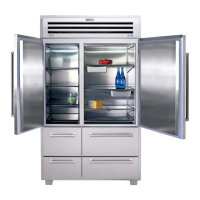
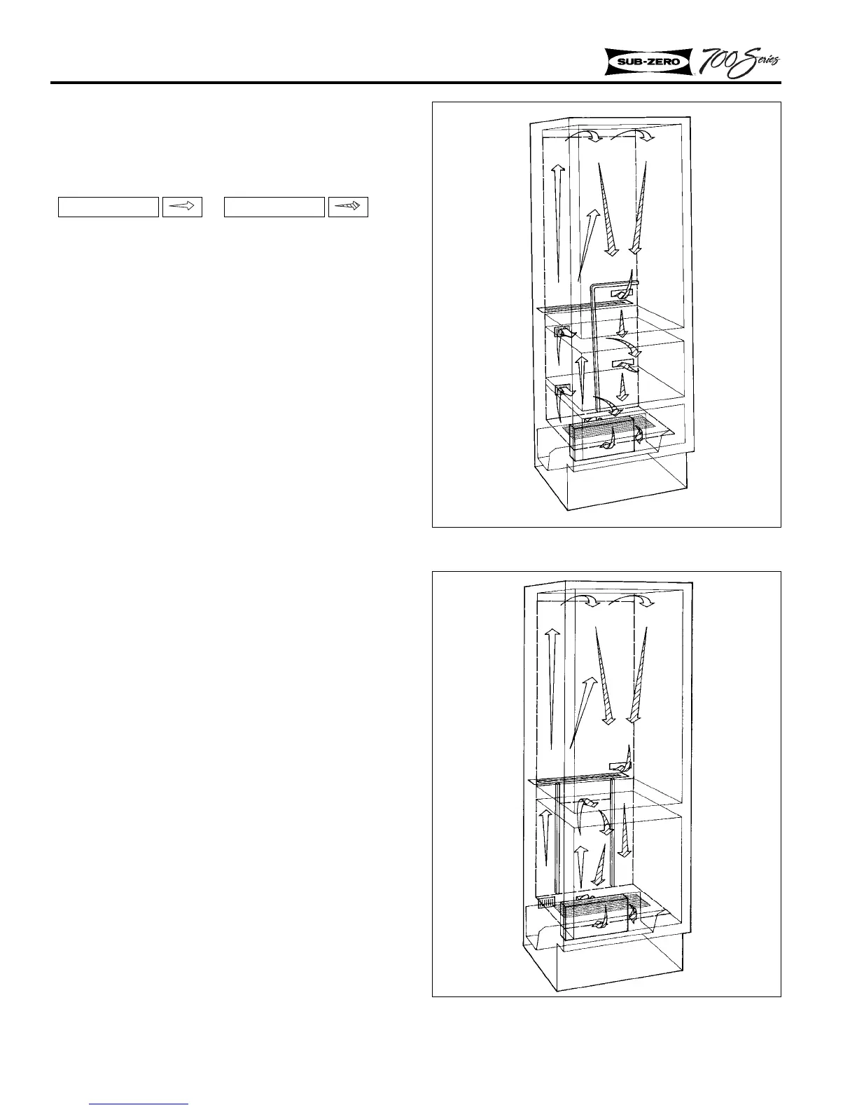
NOTE: In all the following air flow illustrations
the white arrow signifies Pushed Air, while the
shaded arrow signifies Returned Air.
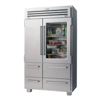
Model 700TR (Figure 3-1)
The temperature for each compartment, or zone, in
the 700TR can be independently controlled (up to
3°F colder than the zone above it) by the air baf-
fle/duct divider system. Depending on the differ-
ent zone requirements, the air baffles in each zone
open and close as needed.
Air to the bottom drawer zone is directed behind
the lower air duct, up the left side and through the
air baffle behind the bottom drawer. The air then
returns to the evaporator sump area through the
vents in the evaporator cover.
Air to the upper drawer zone is directed behind
the lower air duct, up the left side and through the
air baffle behind the upper drawer. Air then
returns through an opening in the lower air duct (at
bottom right of upper drawer zone), back down
behind the right side of the lower air duct to the
evaporator sump area.
Air to the top refrigerator zone is directed behind
the lower air duct, up the left side and continues
up behind the upper duct in the top refrigerator
zone where it is forced out at the top. The air then
returns through an opening at the bottom right
hand corner of the top duct, back down behind the
right side of the lower air duct to the evaporator
sump area.
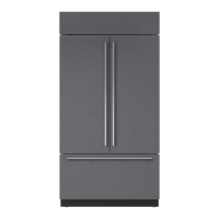
Model 700TC/I (Figure 3-2)
The freezer zone has two vertical duct dividers
behind the lower rear duct which separate the air
to the refrigerator from air to the freezer.
Air to the refrigerator zone is directed through a
baffle in the left side of evaporator sump area, then
ducted up the left side to the refrigerator compart-
ment. Air travels up behind the back duct in the
Figure 3-1. Model 700TR Air Flow
Figure 3-2. Model 700TC/I Air Flow
Return Air
Pushed Air
 Loading...