COMPONENT INFORMATION
2-7
ZONE THERMISTORS
In the 700 series, it is possible to independently control
temperatures in each zone. This is accomplished in
part by thermistors, which are simply resisters that
change resistance as the surrounding temperature
changes. The microprocessor constantly monitors the
thermistor’s electronic signal and, as resistance
changes, the microprocessor electronically reads the
signal as temperature. In turn, the microprocessor initi-
ates compressor and condenser fan run time, evaporator
fan motor run time, when the baffles open and close for
proper air flow, and determines the proper timing and
duration of defrost. Zone thermistor location is
described below, along with an explanation of their
function, and the procedure for their replacement.
Zone Thermistor Location and Removal
MODELS 700TF/I, 700BF/I
The input temperature range in all these freezer models
is from -5°F to +5°F, and is uniform throughout the
cabinet. In other words, there is one zone and one ther-
mistor for that zone. The thermistor is located behind
the upper drawer in the reed switch assembly (Figure
2-15).
1. To replace the thermistor, the complete reed switch
assembly must be replaced. Remove the mounting
screw, tilt the top of the reed switch assembly for-
ward and disconnect the electrical connector.
NOTE: Be sure to check Troubleshooting Guide for
proper thermistor testing procedures.
NOTE: The upper and lower reed switches are not
interchangeable in the models 700 TF/I and 700BF/I
(Figure 2-19).
MODELS 700TR, 700BR
The input temperature range in all these refrigerator
models is from 34°F to 45°F. Each compartment, or
zone, can be independently temperature controlled up
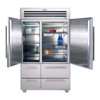
Figure 2-15. Thermistor Location
Figure 2-16. Back Duct Removal
 Loading...