COMPONENT INFORMATION
2-10
3. Detach all four drawer slides by removing four
mounting screws (Figure 2-21).
4. Remove both drawer closers by removing two
mounting screws (Figure 2-22).
5. Remove both reed switches by unscrewing the
mounting screw, tilt the top of the reed switch
assembly forward and disconnect the electrical
connector (Figure 2-17).
6. Now remove three screws at the front and back
of the evaporator cover, then remove the evapo-
rator cover. Remove the air duct retaining
screw by the bottom left corner. Pull the bot-
tom of the air duct forward and disconnect the
electrical connectors to the air baffles, then
remove the air duct from the unit.
NOTE: The baffles are applied with double stick
tape to the back of the air duct and will need to be
pried off.
NOTE: On 700BR the cabinet harness will need to
be disconnected from the air duct assembly by
turning the retaining nut counterclockwise at the
connector.
MODEL 700TC/I
1. Remove both drawer assemblies. Now detach
all four drawer slides by removing four mount-
ing screws (Figure 2-21).
2. Remove the icemaker if applicable.
3. Remove both drawer closers by removing two
mounting screws (Figure 2-22).
4. Remove both reed switches by unscrewing the
mounting screw, tilt the top of the reed switch
assembly forward and disconnect the electrical
connector (Figure 2-17).
5. Remove three screws at the front and back of
the evaporator cover, then remove the evapora-
tor cover. Remove the air duct retaining screw
by the bottom left corner. Pull the bottom of
the air duct forward and remove the air duct
from the unit.
The air baffle or baffle mount assembly (styro-
foam block) is located at top left of the evapo-
rator sump area (Figure 2-20). Lift the baffle
mount assembly up and unplug the electrical
connection.
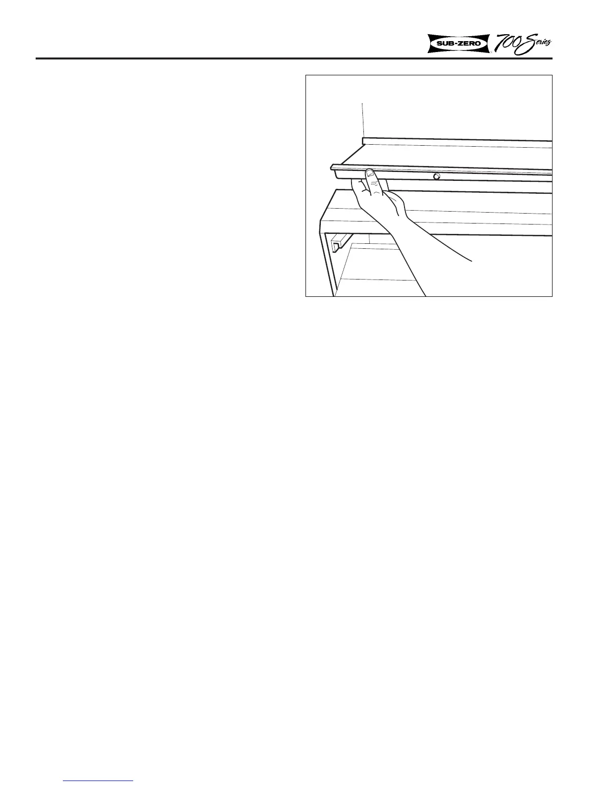
Figure 2-23. Center Divider
 Loading...