COMPONENT INFORMATION
2-5
2. To open the upper control panel front, grasp the
outer top corners and pull down.
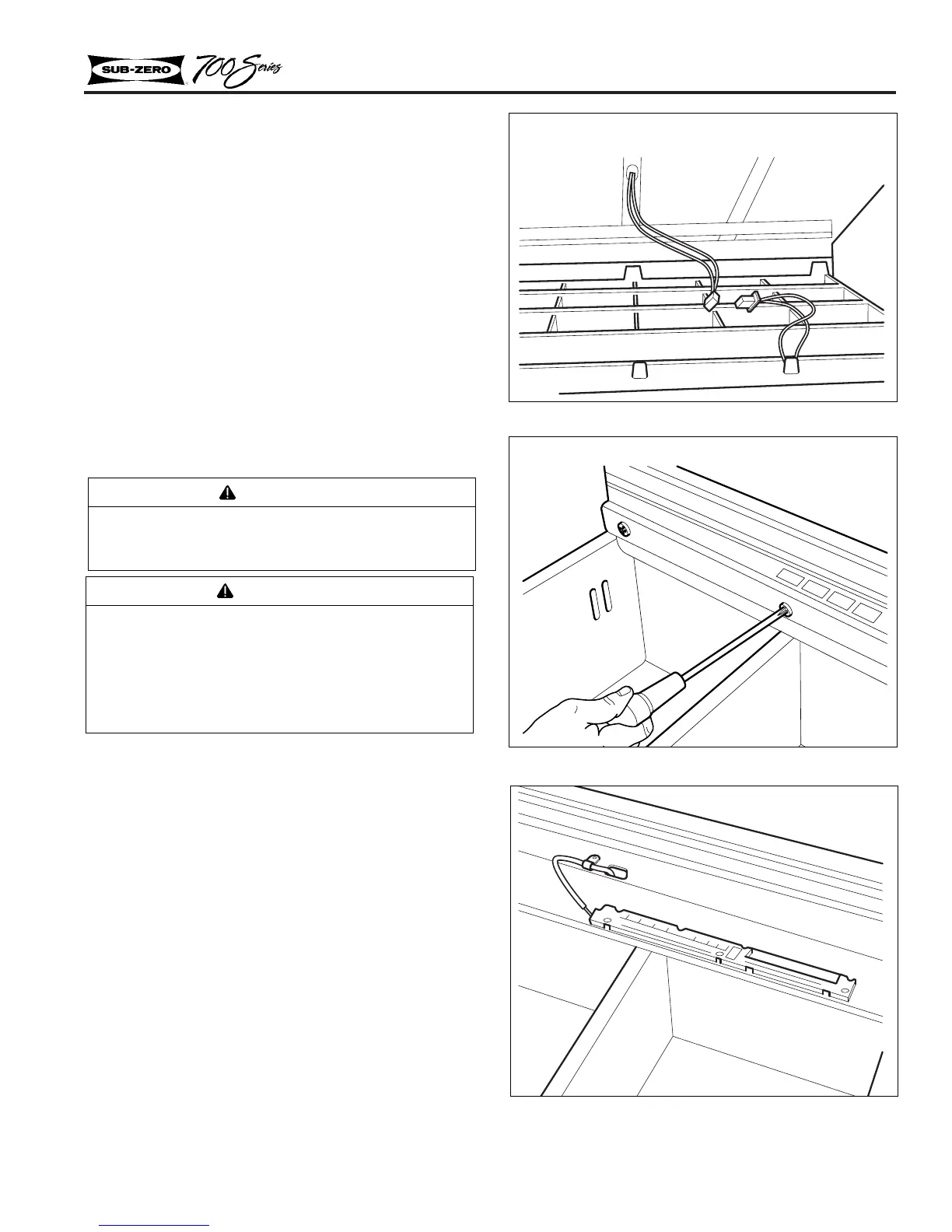
3. Disconnect the leads supplying power to the
control panel. Remove the three front mount-
ing screws. The center screw is the ground
screw (Figure 2-9).
4. Pull the complete upper control assembly for-
ward and down, (which includes the control
board, glass light diffuser, reflectors and halo-
gen lamps (Figure 2-9).
5. Disconnect electrical supply at the top of upper
control panel assembly (Figure 2-10).
NOTE: Reverse steps 1 - 5 to reassemble. Make
sure ground screw is used at front center only.
Control Panel Removal
Models 700BR, 700BF/I
1. Remove the three screws inside top drawer
assembly (Figure 2-11). Then tilt control panel
towards back of the drawer tub.
2. Now disconnect the power supply to the control
panel (Figure 2-12).
NOTE: Reverse steps to reassemble.
CAUTION
Do not touch lamp with bare hands. Oils from
skin will reduce the life of the lamp. If lamp is
touched with bare hands, clean lamp with
denatured alcohol and wipe dry with lint free
cloth.
WARNING
Halogen lamps are extremely hot! Allow lamp
to cool before attempting to handle.
Figure 2-10. Control Panel Electrical Supply
Figure 2-11. Control Panel Screws
Figure 2-12. Control Panel Power Supply
Models 700BR, 700BF/I
Models 700BR, 700BF/I
 Loading...