subzero.com | 9
Panel Installation
SIDE PANEL
When installing a custom side panel, an accessory kit is
required and is available through an authorized Sub-Zero
dealer. Stainless steel side panels are also available from an
authorized Sub-Zero dealer.
IMPORTANT NOTE: The use of side panels may change
the width of the opening.
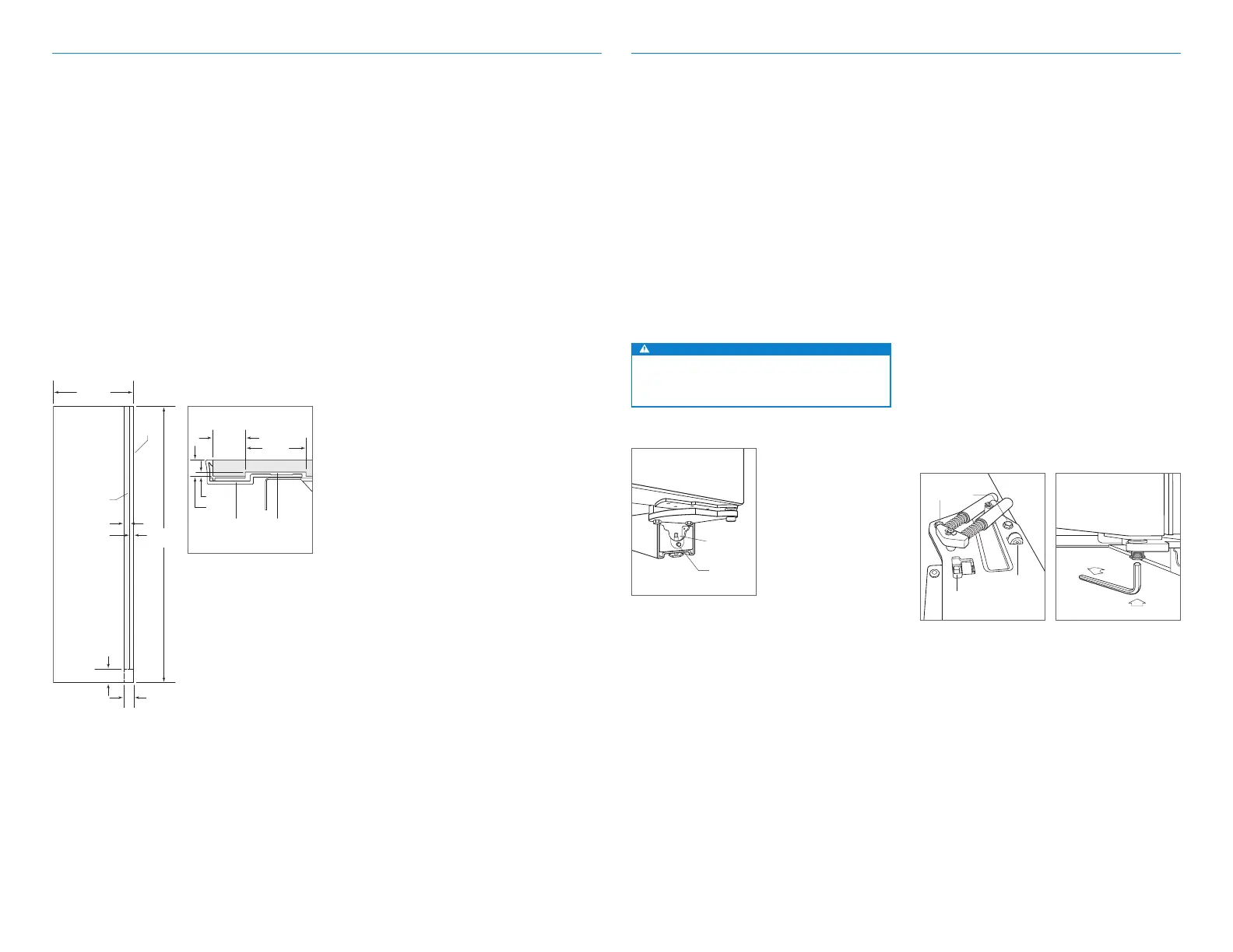
A custom side panel must be a minimum of 610 mm deep
and 13 mm thick. Routing will be necessary for the side
panel to fit flush against the side of the unit. Refer to the
illustrations below.
IMPORTANT NOTE: The height of the side panel will vary
with the height of the grille. Verify the finished height
before modifying the panels.
Installation
Alignment
LEVELING
Once the unit is in position, turn the front leveling legs
clockwise to adjust the height. The rear height adjustment
can be made from the front of the roller base. Using a ⁄"
socket, turn the ⁄" hex bolt clockwise to raise the unit or
counterclockwise to lower. Use the lowest torque setting
when using a power drill. Do not turn the rear leveling legs
by hand. Refer to the illustration below.
When the unit is properly leveled, door adjustments are
less likely to be necessary.
IMPORTANT NOTE: Level the unit to the floor, not the sur-
rounding cabinetry. This could aect the operation of the
unit, such as door closing.
WARNING
To reduce the possibility of the unit tipping forward,
the front leveling legs must be in contact with the
floor.
DOOR ADJUSTMENT
The door can be adjusted in and out, side to side tilt, and
up and down.
To make adjustments, slightly loosening the two upper
hinge bolts on the upper hinge plate using a ⁄" wrench.
Refer to the illustration below.
In-and-Out Adjustment: For a left-hinge door, using a
⁄" allen wrench, turn the adjustment bolt clockwise to
bring the handle side of the door inward, and counter-
clockwise to move the handle side outward. Reverse direc-
tions for a right-hinge door.
Side-to-Side Tilt Adjustment: For a left-hinge door, using
a ⁄" wrench, turn the adjustment bolt clockwise to raise
the handle side of the door, and counterclockwise to lower
the handle side. Reverse directions for a right-hinge door.
Up-and-Down Adjustment: For a left-hinge door, using
a ⁄" allen wrench, turn the adjustment bolt clockwise to
raise the door and counterclockwise to lower. Refer to
the illustration below. Reverse directions for a right-hinge
door.
FRONT
LEVELING LEG
REAR
ADJUSTMENT
Leveling
UPPER
HINGE BOLTS
SIDE-TO-SIDE
TILT ADJUSTMENT
IN-AND-OUT
ADJUSTMENT
Door adjustment bolts
Up-and-down door adjustment
Panel Installation
2134
mm
610 mm
OPTIONAL
TOE KICK
CUT-OUT
102 mm
48 mm
25 mm
ROUT TO
3 mm
FRONT
OF SIDE
PANEL
67 mm
MAIN
FRAME
SIDE PANEL
ROUTING
25 mm
48 mm
3 mm
13 mm
Side panel dimensions
Routing detail