EC2000 Controller Operation Manual 1: Description
88290022-798 R03 3
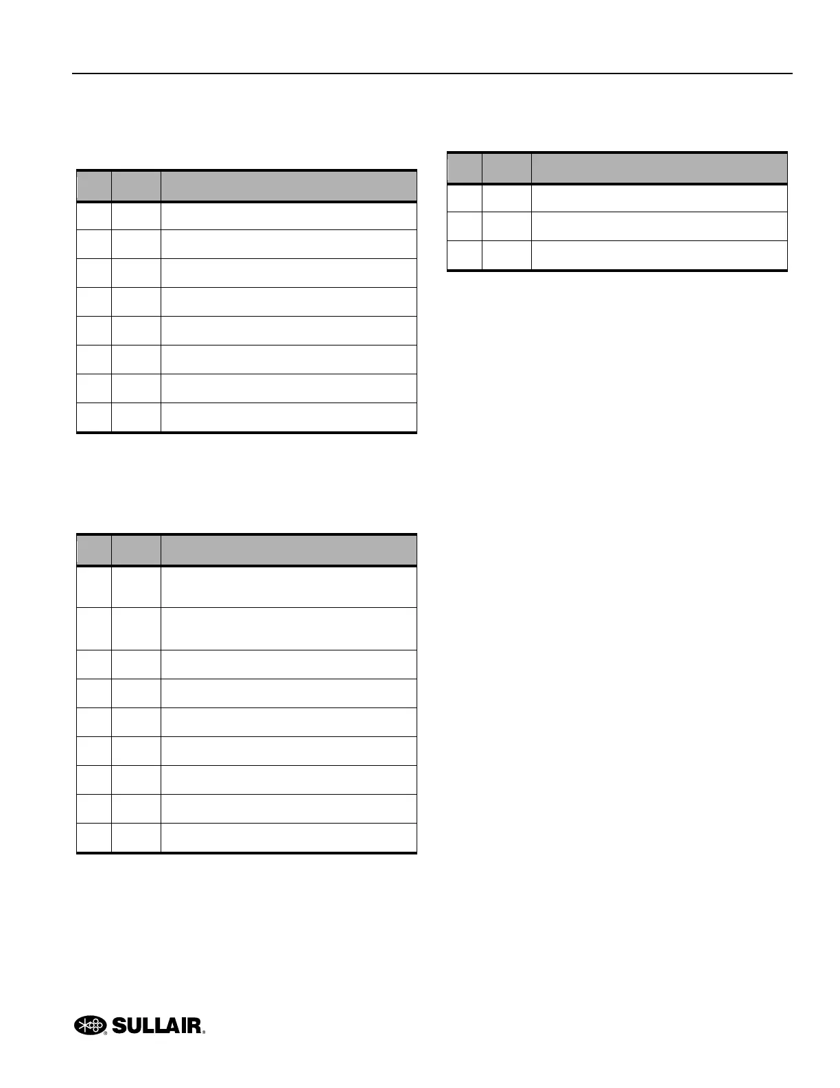
Table 1-2: JP4—input signal quantity and
RS485 port (8 pins)
Pin Name Description
1 DI0 Definable input (normal close)
2 DI1 Definable input (normal close)
3 DI2 Definable input (normal close)
4 DI3 Definable input (normal close)
5 DI4 Emergency stop signal input (normal close)
6 GND Input common
7 A RS485 port
8 B RS485 port
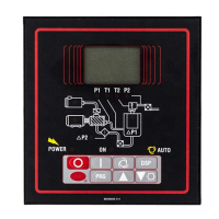
Table 1-3: JP3—binary output quantity (9
pins)
Pin Name Description
1 ACIN0
Contactor power input 1 (common output of
internal relay
2 ACIN1
Contactor power input 2 (common of internal
RC)
3 VD Loading solenoid valve output
4 KF Fan motor contactor output
5 RCS Y contactor RC output
6 KS Y contactor output
7 RCD ∆ contactor RC output
8 KD ∆ contactor output
9 KM Main contactor output
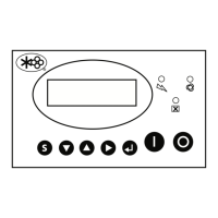
Table 1-4: JP5—power input (3 pins)
Pin Name Description
1 XGD To ground
2 ACIN0 ~25V power input (same with R-phase)
3 ACIN1 ~25V power input (same with S-phase)