Section 2
DESCRIPTION
8
compressor unit when the compressor is shut
down. When the compressor is operating, the fluid
stop valve is held open by air pressure from the
compressor unit allowing a free flow of fluid from
the receiver/sump back tothe compressor unit. On
shutdown, the compressor unit pressure is re-
duced, causing thefluidstop valve toclose andiso-
late the compressor unit from the cooling system.
Water---cooled versions of the compressor have a
water---flow regulating valve (not shown) which op-
erates to conserve water during periods of varying
load on the compressor. This same valve automati-
cally shuts off the water supply when the compres-
sor is shut down. In addition, water---cooled mod-
els have a water pressure switch to prevent opera-
tion with inadequate water pressure.
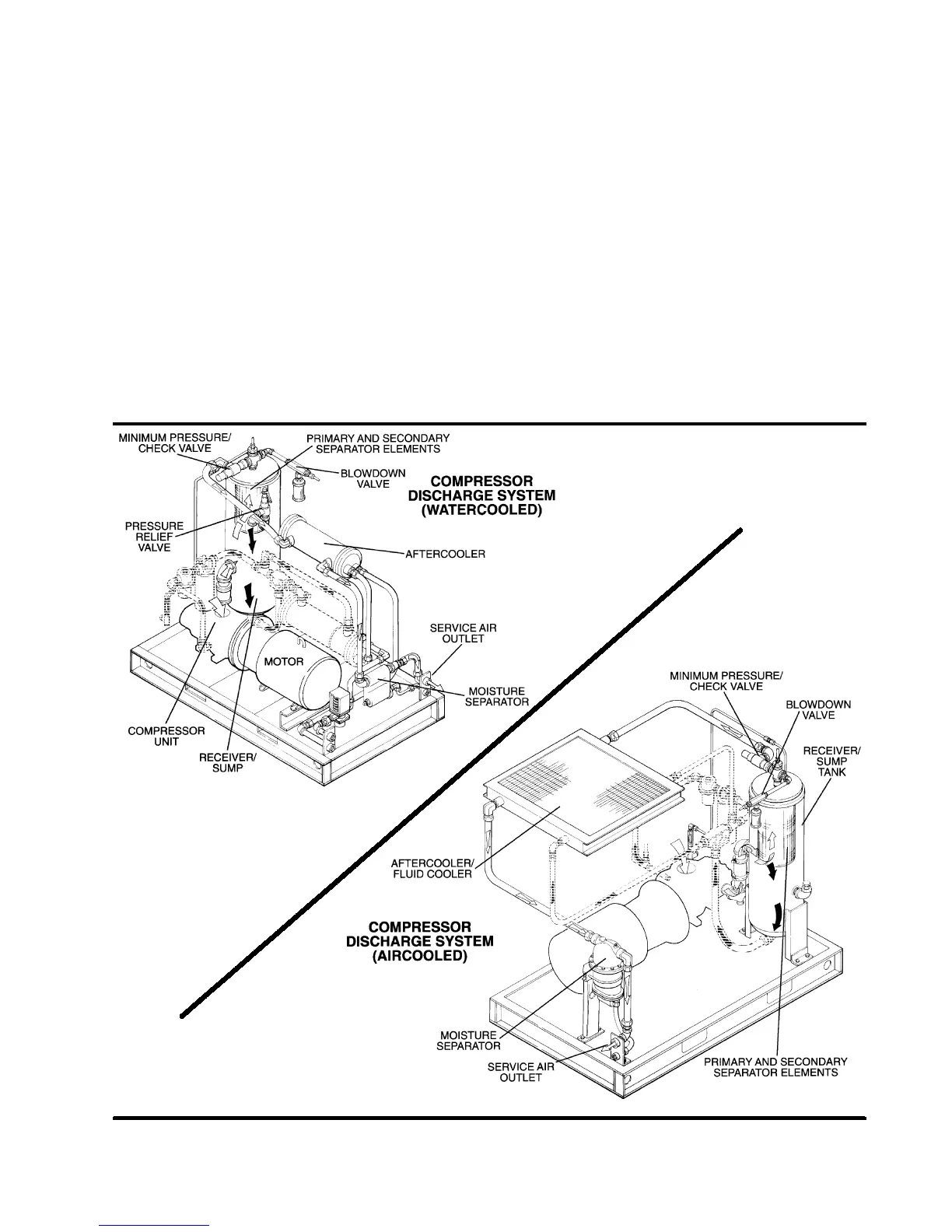
2.5 COMPRESSOR DISCHARGE SYSTEM, FUNC-
TIONAL DESCRIPTION
.
Refer to Figur e 2 --- 4 . The c ompr essor unit dis -
charges the compressed air/fluid mixture into the
combination receiver/sump. The discharge check
valve prevents air in the receiver from returning to
the compression chamber after the compressor
has been shut down.
The receiver has three basic functions:
1. It acts as a primary fluid separator.
2. Serves as the compressor fluid sump.
3. Houses the final fluid separator.
The compressed air/fluid mixture enters the receiv-
Figure 2---4 Compressor Discharge System (Typical)

 Loading...
