Section 2
DESCRIPTION
12
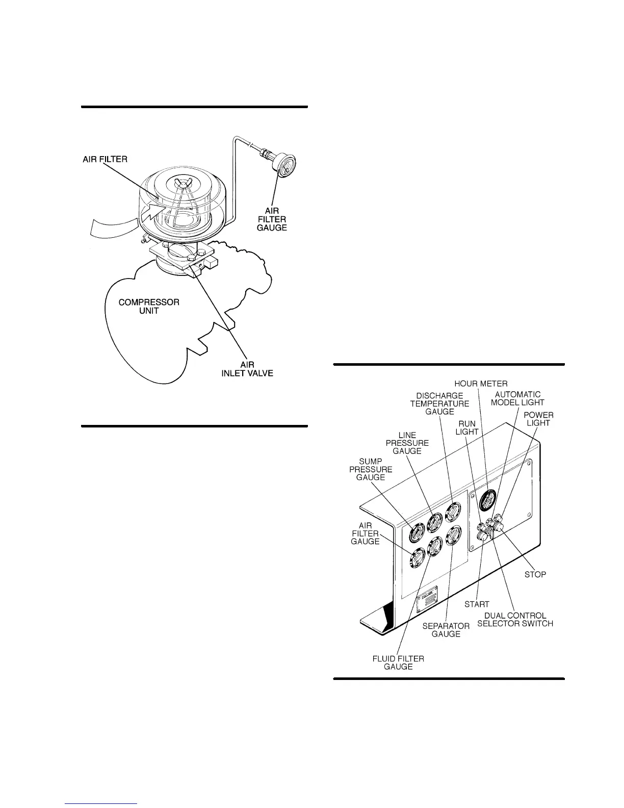
Figure 2---6 Compressor Air Inlet System
restriction gauges
,alongwith
ST ART
and
STOP
pushbuttons and an
hourmeter
.
Refer to Figur e 2 --- 7 f or l oc a tions of the fol l owing in -
dicators and controls:
S
and 100HP
The
line (terminal) pressure gauge
is connected to the dry side of the receiver down-
stream from the check valve and continually moni-
tors the air pressure.
S
The
sump pressure gauge
continually monitors
the sump pressure at the various load and/or un-
load conditions.
S
The
discharge temperature gauge
monitors
the temperature of the air leaving the compressor
unit. For both air---cooled and water---cooled com-
pressors the normal reading is approximately
180
_
F(82
_
C) when the ambient temperature is
less than 80
_
F(27
_
C).
S
The
air filter restriction gauge
monitors the con-
dition of the air intake filter and shows in the red
zone(20”to30”water[51to76cm])when filterser-
v ic e is r equir ed ( s ee Figur e 2 --- 6 ) .
S
The
ST ART
pushbutton turns the compressor on.
S
The
STOP
pushbutton turns the compressor off.
S
The
hourmeter
records cumulative hours of op-
eration for the compressor and is useful for plan-
ning and logging service operations.
S
The
separator maintenance gauge
monitors
the condition of the separator elements and shows
in the red zone when the element restriction is ex-
cessive.
S
The
fluid filter maintenance gauge
monitors
the condition of the bearing filter element and
shows in the red zonewhen the element should be
changed.
S
The
red light
on the instrument panel indicates
when power to the compressor is supplied.
S
The
greenlight
indicates whenthe compressor is
running.
S
The optional
dual control package
is supplied
with an amber auto mode indicator light to indicate
that the unit is running in the automatic mode. A
position selector switch provides selection be-
tween hand operation and automatic control.
Figure 2---7 Instrument Panel Group

 Loading...
