Installation, Operating and Maintenance Instructions (Original Instructions) 11
VMS Vertical Multistage Pumps
11
Any other or further use of the pump is not in conformity with its intended use. Sulzer does not accept any
liability for any damage or injury that results from this. The pump is produced in accordance with the current
standards and guidelines. Use the pump only in a perfect technical state, in conformance with the intended use
described below.
The ”intended use” as laid down in ISO 12100:2010 is the use for which the technical product is intended
according to the specications of the manufacturer. The use of the product has been described in the sales
brochure and in the user manual. Always observe the instructions given in the user manual. When in doubt the
product must be used as becomes evident from its construction, version and function.
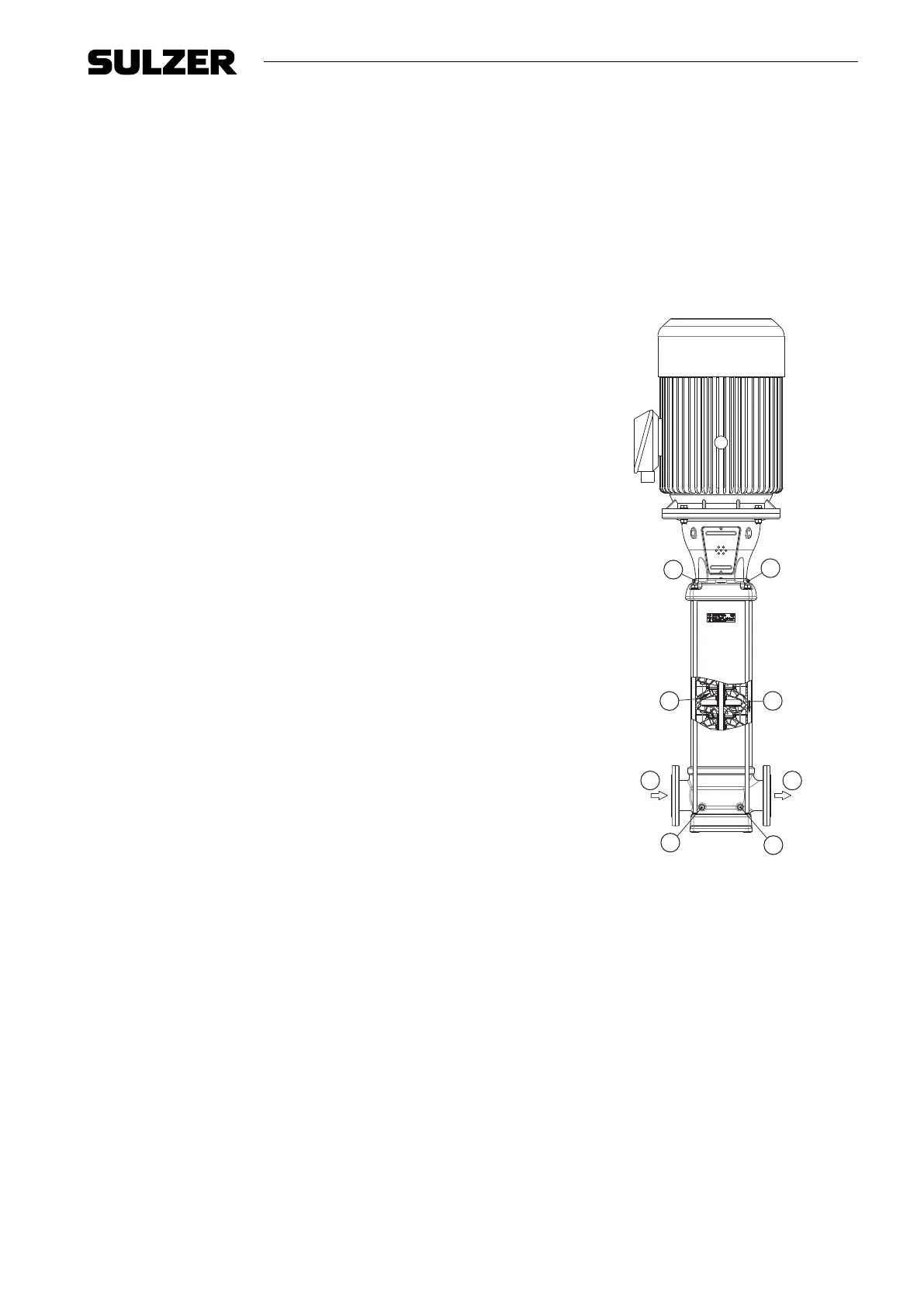
5.5 Operation
The rotating impeller causes the pressure at the inlet of the impeller to
drop. This decrease in pressure creates the ow through the suction
connection (A). Every stage (B) consists of an impeller and a diusor.
The capacity of the pump is determined by the size of the passageway of
the stage. The pressure of the stage is determined by the diameter of the
impeller.
Because of the modular type of construction it is possible to choose the
number of impellers most suited to the required duty point. After leaving
the last impeller the medium ows between the pump stages and the outer
sleeve (C), and exits the pump at the discharge connection (D).
5.6 Measuring, draining and venting
The pump is provided with plugs for measuring, draining and venting.
Connection (E) is meant to drain the inlet part of the pump, or to measure
the inlet / suction pressure using a G ¼" connection.
Connection (F) is meant to drain the outlet part of the pump, or to measure
the discharge pressure using a G ¼" connection.
Connections (G) are meant to vent the pump system when the pump is not
in operation, or to measure the discharge pressure of the pump using a
G
3
/8" connection.
D
A
E
F
G
G
B
C
1561-00
Figure 4. VMSF 85
5.7 Modular selection
For an optimal match with the application, the pump is assembled out of modules which are selected depending
on their specications.
The basic modules are:
• Basic pump model: denes the capacity and head, the basic material and allowable pressures and
temperatures.
• Connections: denes the connection size, pressure class and allowable temperatures.
• Sealings: denes material of the elastomers, shaft seal type and allowable pressures and temperatures.
• Electric motor: denes all requirements of the motor such as size, power, supply voltage, frequency and
possible motor accessories.