12 Installation, Operating and Maintenance Instructions (Original Instructions)
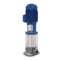
VMS Vertical Multistage Pumps
12
5.8 Working range
The working range depends on the basic hydraulic design, the type of connection, and sealings. The module in
the pump with the strictest specication determines the allowable pressure and temperature of the medium in
the pump. The general working specications can be summarised as follows:
Table 5. Generalworkingrangespecication
Pump type VMS Note
1. Avoid freezing the pump.
2. If the ambient temperature exceeds this value, or the
motor is located more than 1000 m above sea level,
the motor cooling is less eective and could require an
adapted motor power. Please contact your supplier for
more detailed advice.
3. Deviation in viscosity and/or density could require an
adapted motor power. Please contact your supplier for
more detailed advice.
4. Pumps that are intended for 50 Hz operation, may not
be connected to 60 Hz power supply.
5. Frequent start/stops, in particular in combination
with higher pressure dierences (Δp), may result in a
shortened product lifetime. Consult your supplier for
such applications.
6. Only the noise emission of the motor is documented.
Ambient temperature [°C] -20 up to 40
1, 2
Minimum inlet pressure NPSH
req
. + 1 m
Viscosity [cSt] 1 - 100
3
Density [kg/m
3
] 1000 - 2500
2
Cooling Forced motor cooling
Minimum frequency [Hz] 30
Maximum frequency [Hz] 60
4
Maximum number of starts See motor data sheet
5
Noise emission See motor data sheet
6
Allowable size of solids pumped 5 μm to 1 mm
ATTENTION! The temperature dierence between the medium and the pump should never exceed
60 °C. To avoid any chance of a thermal shock the pump must be lled / heated up
slowly in any case where the dierence between the pump and the medium is more
than 30 °C.
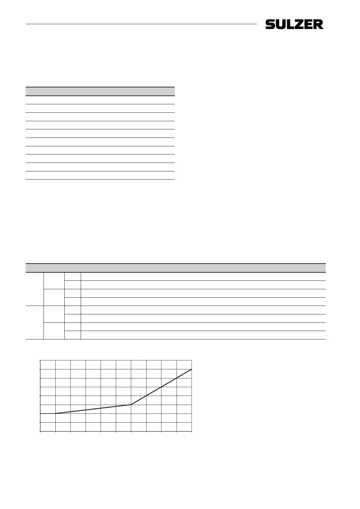
For minimum/maximum ow at medium temperature of 20 °C see Table 6, ”Minimum/maximum capacity (Qmin/
max)”; for higher temperatures see Figure 5, ”Minimum capacity vs. temperature (in % of Q optimum)”.
Table 6. Minimum/maximum capacity - Qmin/max [m
3
/hr]
Size 2 4 6 10 15 25 40 60 85 125 H6
50 Hz
2-pole
Min. 0.2 0.4 0.6 1.1 1.6 2.8 4.0 5.3 8.5 30.0 0.8
Max. 3.3 6.5 9.0 13.2 22.5 35.0 54.0 57.0 110.0 160.0 8.6
4-pole
Min. - - - 0.5 0.8 1.4 1.9 2.6 4.3 15.0 -
Max.
-
- - 6.6 11.3 17.5 27.0 38.0 53.9 80.0 -
60 Hz
2-pole
Min. 0.2 0.5 0.8 1.3 2.0 3.1 4.9 6.4 10.2 36.0 0.7
Max. 4.0 7.8 10.8 15.8 27.0 42.0 65.0 92.0 132.0 192.0 8.6
4-pole
Min.
-
- - 0.6 1.0 1.6 2.3 3.2 5.1 18.0 -
Max.
-
- - 7.9 13.5 21.0 32.5 46.0 65.1 96.0 -
0
5
10
15
20
25
30
35
40
Q [%]
40 50 60 70 80 90
T[ºC]
100 110 120 130 140
1562-00
Figure 5. Minimum capacity vs. temperature (in % of Q optimum)