Installation, Operating and Maintenance Instructions (Original Instructions) 19
VMS Vertical Multistage Pumps
19
1565-00
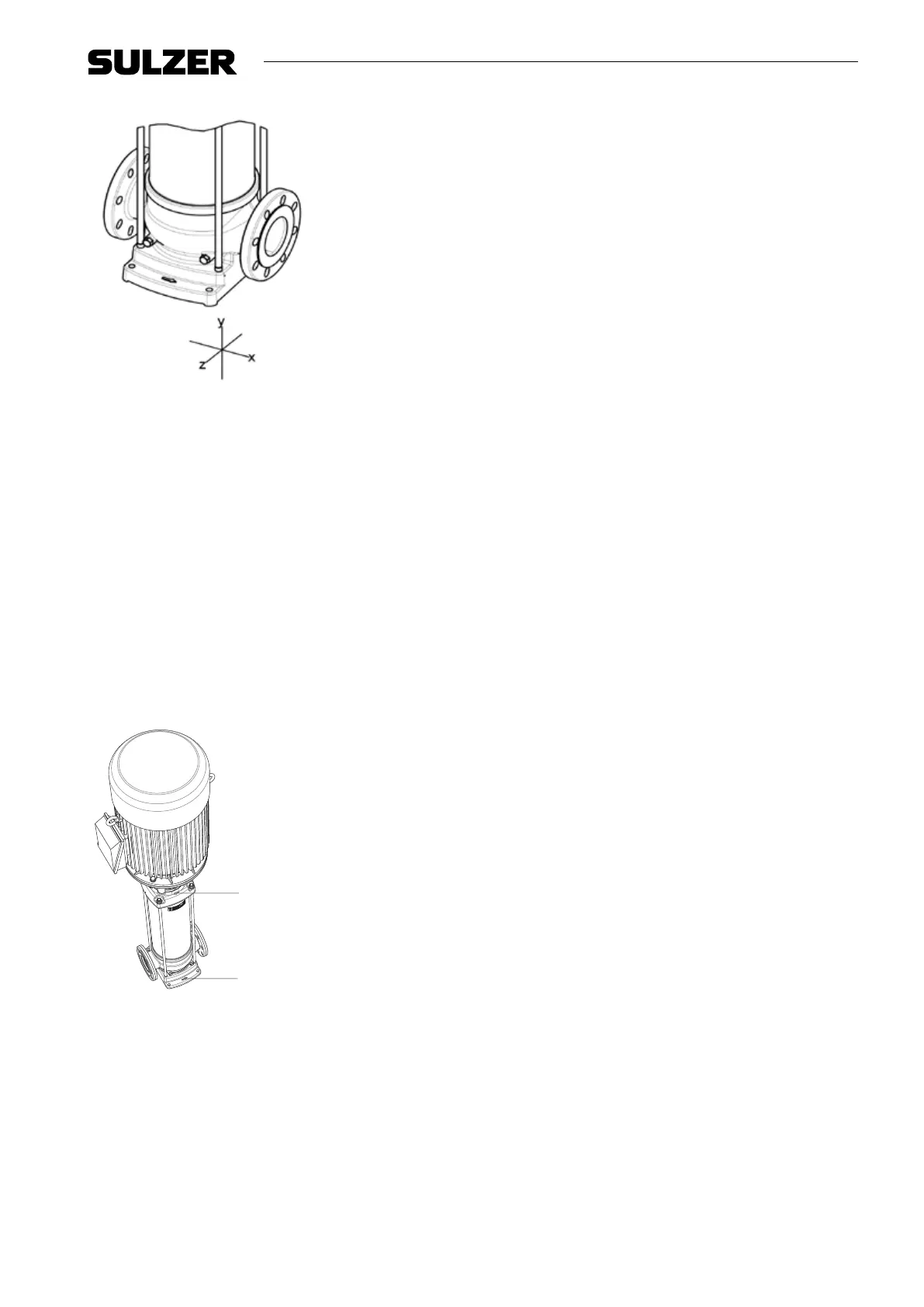
Figure 8. Allowable forces
ATTENTION! Pumps which do not stand steady or stable on their own, should be mounted on a
rigid and stable base.
ATTENTION! Locate the pump at the place with the lowest risk for noise nuisance.
1. Place and install the pump on a level, stable surface in a dry and frost-free room.
2. Make sure that sucient air can reach the cooling fan of the motor. For this purpose the free space above
the cooling fan should be at least one quarter of the diameter of the fan cover air intake.
3. Install the pump with counter anges. For pumps with non-standardised connections, counter anges are
delivered separately.
4. It is advised to install a shut o valve on the supply and on the delivery connection of the pump.
5. To avoid medium owing back through the pump, when idle, make sure a non-return valve is installed.
6. Make sure that the inlet of the pump is never clogged.
7.1.1 Indicators
B
A
1566-00
Figure 9. Pump indicators
The arrow (A) on the pump foot indicates the ow direction of the liquid. The arrow (B) on the top bracket
indicates the rotating direction of the motor.
7.1.2 Install bypass
Install a bypass if the pump operates against a closed valve. The required capacity of the bypass is at least
10% of the optimum volume ow. At high operating temperatures a higher volume ow is required. Refer to
the table ”Minimum volume ows” in the paragraph 5.8 ”Working range”, and Fig. 5, ”Minimum capacity vs.
temperature (in % of Q optimum)”.