22 Installation, Operating and Maintenance Instructions (Original Instructions)
VMS Vertical Multistage Pumps
22
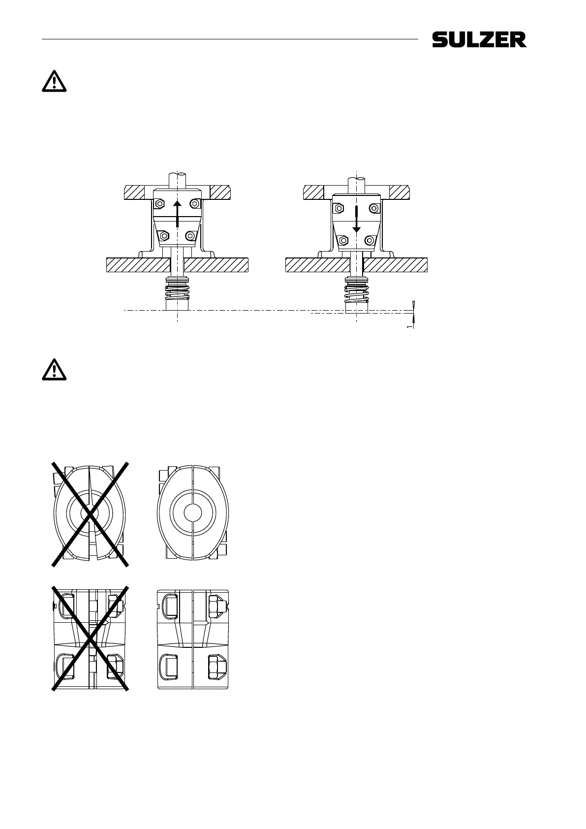
Correct seal adjustment max. 1.5 mm higher than the lowest position.
ATTENTION! For motors of 11 kW or higher, block the rotor when adjustments are made to the
coupling. This ensures that the rotor is not lifted out of its bearings.
8. For pump series VMS H 6: use a sucient tyre iron to lift the coupling (and hydraulic assembly) to the
maximum upwards position and lower it 1 mm from this position.
1569-00
Figure 12. Positioning the seal
Correct seal tension max. -1.0 mm lower than the maximum upwards position.
ATTENTION! For motors of 11 kW or higher, block the rotor when adjustments are made to the
coupling. This ensures that the rotor is not lifted out of its bearings.
9. Fully tighten the couplings at the given torque (see Table 15, “Torques”). Make sure that the gaps between
the couplings are equally divided on both sides (see drawing).
1570-00
Figure 13. Position of the coupling
10. Attach the coupling guards (681) with the socket head cap screws (914.05) to the motor stool (341).
11. Connect the power supply. see § 7.3 Electrical installation.