Seite 4 BB_ENG_991305_04_16
BUDDYBOX Operating Manual
4. Connection of other transmission components
Assembly is carried out using the central bores in the ends of the shaft or by heating the parts
to be mounted to a maximum of 100°C. The shafts have been tted with keyways to DIN 6885,
sheet 1. Bores of the parts to be tted on the shafts should be according to the tolerances given
in the respective catalogue. A locking screw or similar is to be used to prevent any axial move-
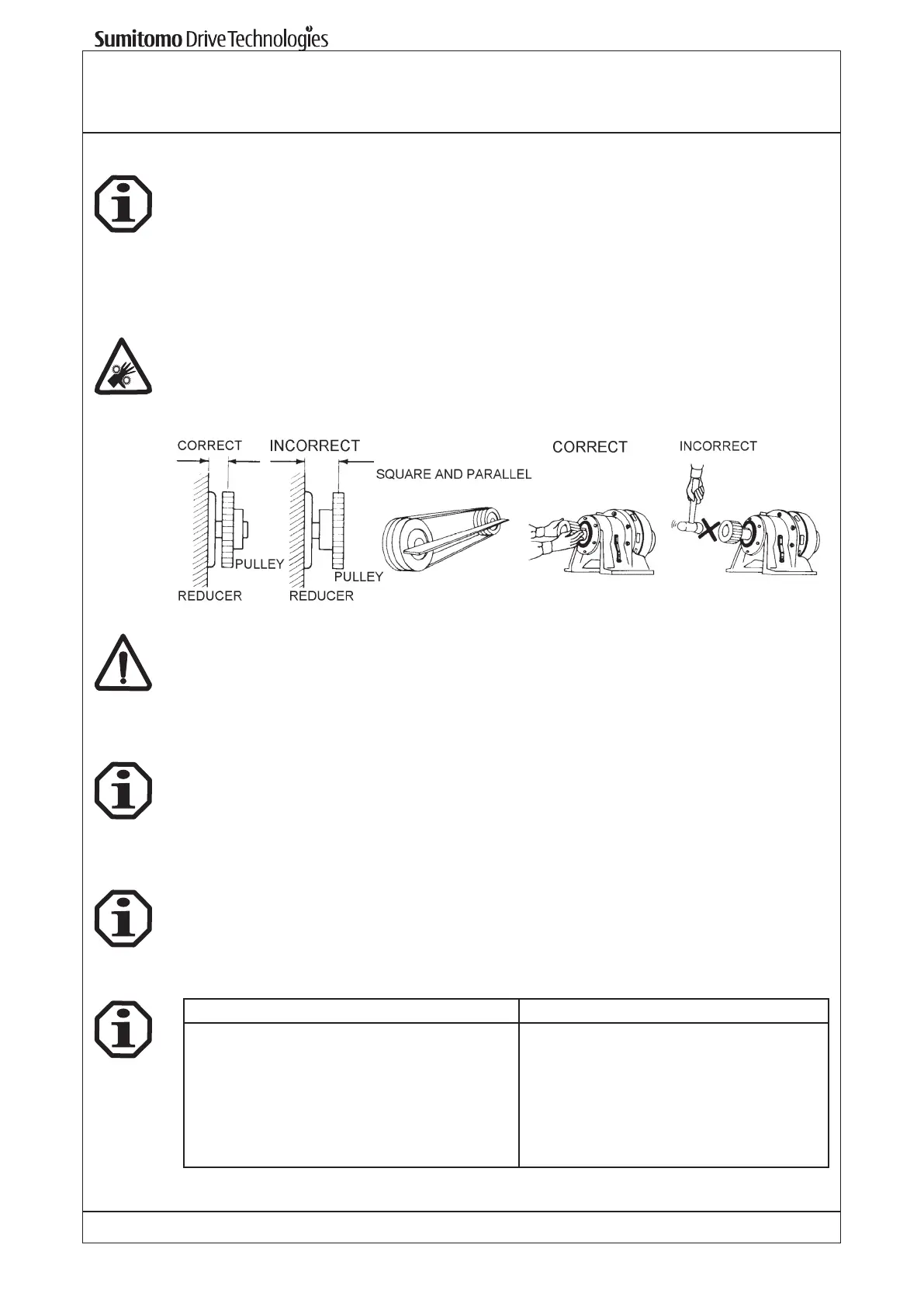
ment. Chainwheels, discs or gear wheels must be located as close to the bearing as possible
(see illustration below to keep the radial loads as small as possible). If pinions or chains etc.
are used, the drive should be installed so that the unit location fastening act against the applied
radial load. In the case of speed reducers with hollow high speed shafts, MoS2 paste or spray
(e.g. Molykote) is to be applied to the motor shaft before it is connected.
It is the responsibility of the user to provide guards for all exposed input and output components
such as pulley, couplings, etc.!
Clutches, discs, gear wheels, chains, etc. should be mounted on the reducer shafts carefully.
Do not force them onto the shafts as this could damage the gearbox bearings.
5. Gear or gearmotor installation
5.1 Necessary tools
– Screw wrench set
– Torque wrench for fastening screws on foot or ange housing, motor adaptor, clamp coupling,
etc.
– Pulling on device
– Mounting shims
– Corrosive protection (e.g. MoS2-Paste)
Lubrication ttings (air breather, oil sight glass) provided apart should be assembled as indicated
prior installation of the gear.
5.2 Assembly tolerances for gear or gearmotor
Shafts Flanges
Input shaft k6 for ø < 30 mm
h6 for ø ≥ 30 mm
Output shaft k6 for ø ≤ 50 mm
h6 for ø > 50 mm
H7 for slow speed hollow shaft
High speed hollow shaft F7
Centre boring according to DIN 332, Form DR
Centering shoulder tolerances according to
DIN 42948
IEC-Input ange H8
Output ange h6