Seite 10 BB_ENG_991305_04_16
BUDDYBOX Operating Manual
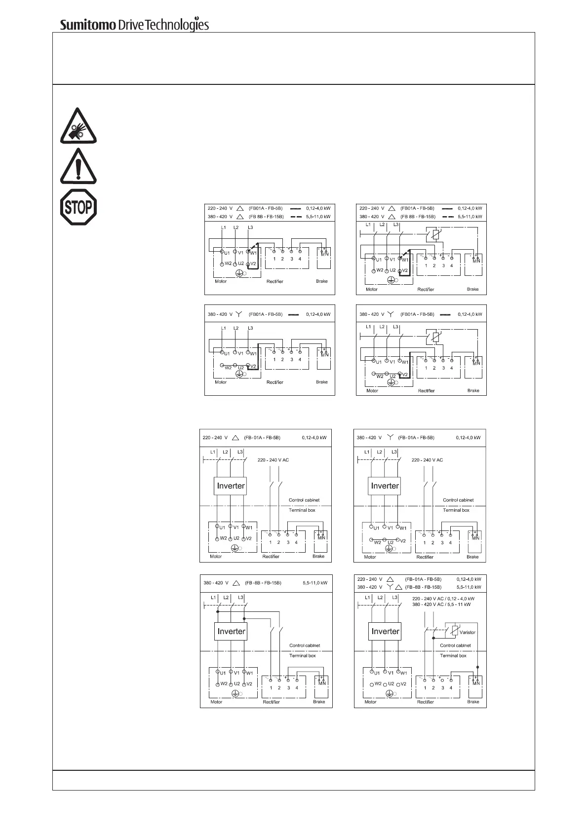
6.6 Brake motor
Connection of brake motors should be according to the following circuit diagrams.
The brake is already wired to the motor at delivery. For a separate power supply to the brake
please disconnect the U1 - 2 and V2 - 1.
The control voltage for the brake is indicated at the rating plate.
For a fast acting brake (de-switching) a separate cable to an external contact is necessary.
The contact must be protected with a varistor.
Standard brake Fast acting brake
For motors driven by an inverter, the brake must be supplied separately, as shown below: