Seite 7 BB_ENG_991305_04_16
BUDDYBOX Operating Manual
5.6 Installation with Taper Grip® Bush
1. Check the size and condition of the shaft to which the reducer will be tted. Maximum toler-
ance is h11 although this should be improved upon where possible. Ensure the shaft and
Taper-Grip® Bush bore are free from burrs and corrosion. Clean both bore and shaft with
solvent to remove all traces of grease and oil.
2. Lightly oil the screws and insert into the Taper-Grip® Bush ensuring they do not project be-
yond the rear face.
3. Fit the thrust collar onto the Taper-Grip® Bush, ensuring it is located on the spigot immedi-
ately behind the ange. Screw the Taper-Grip® Bush into the hub in a clockwise direction
until the thrust collar is trapped between the ange and the reducer hub.
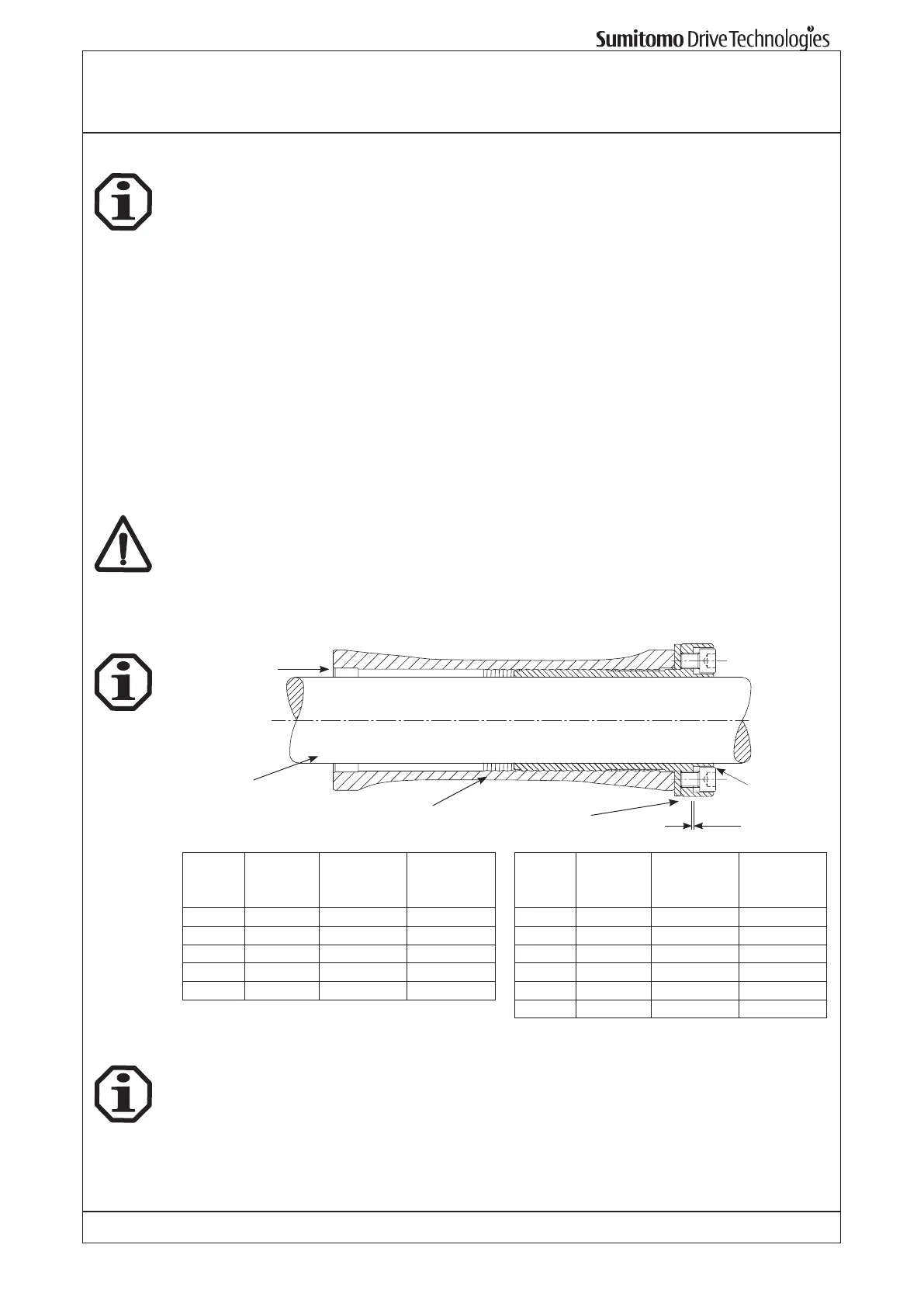
4. Unscrew the bush until a gap of approx. 1 mm is seen between the ange and the thrust
collar (see diagram). Tighten all screws until they are nger tight. On reducers with a keyslot
on the end of the hub, ensure that a screw is NOT positioned over the keyslot.
5. Slide the reducer onto the shaft at least as far as the counter bore, if present, in the Taper- Grip® Bush.
Gradually tighten each screw in turn to the torque levels shown below. If the shaft has
passed through the counter bore, grease ll the cavity at the shaft end to prevent the build
up of corrosion.
6. After the reducer has been running for 20 or 30 hours, re-torque the screws to the values in
the table below.
Screw torques should be subsequently checked at normal service intervals (i.e. every 6
months).
Hollow gear
shaft with inner
grip
1 mm
Bush with
outer grip
Machine shaft
Thrust collar
Grease
BBB3
Size
Taper-
Grip®
Size
Screw
Qty x Size
Screw
Torque
[Nm]
HBB
Size
Taper-
Grip®
Size
Screw
Qty x Size
Screw
Torque
[Nm]
3A E 6 x M12 75 Z C 6 x M10 31
3B F 6 x M12 140 A E 6 x M12 51
3C G 6 x M16 250 B F 6 x M12 51
3D H 6 x M16 300 C G 6 x M16 128
3E J 6 x M16 300 D H 6 x M16 200
E J 6 x M16 200
5.7 Removal of Taper-Grip® Bush
Slacken each screw gradually until they are free from the thrust collar. Give the Taper-Grip®
bush a sharp tap with a mallet to break the taper, this will free the reducer. Finger tighten two
of the screws against the thrust collar to prevent the Taper-Grip® bush locking in the opposite
direction as the reducer is removed from the shaft.