Seite 8 BB_ENG_991305_04_16
BUDDYBOX Operating Manual
6. Electrical installation
6.1 Safety advice
Installation, start up and servicing should only be done by qualied personnel.
Before commencing upon the servicing of the motor or the gearmotor, particularly
before opening covers to active parts, the main electrical supply must be discounted.
Please follow the ve safety rules according to DIN VDE 0105.
The motors comply with the low voltage directives 2014/35/EG.
6.2 Range of use
The motors are totally enclosed fan cooled. Standard protection is IP55, and with brake IP 44.
Ambient temperature: -10° . . . +40°C
Ground level: < 1000 m
Winding is insulation class F (150°C). It is normal for the reducer to operate at a housing
temperature of up to 100°C. Therefore, any contact with them must be prevented. Temperature
sensitive parts must never be fastened to or be in contact with the motor.
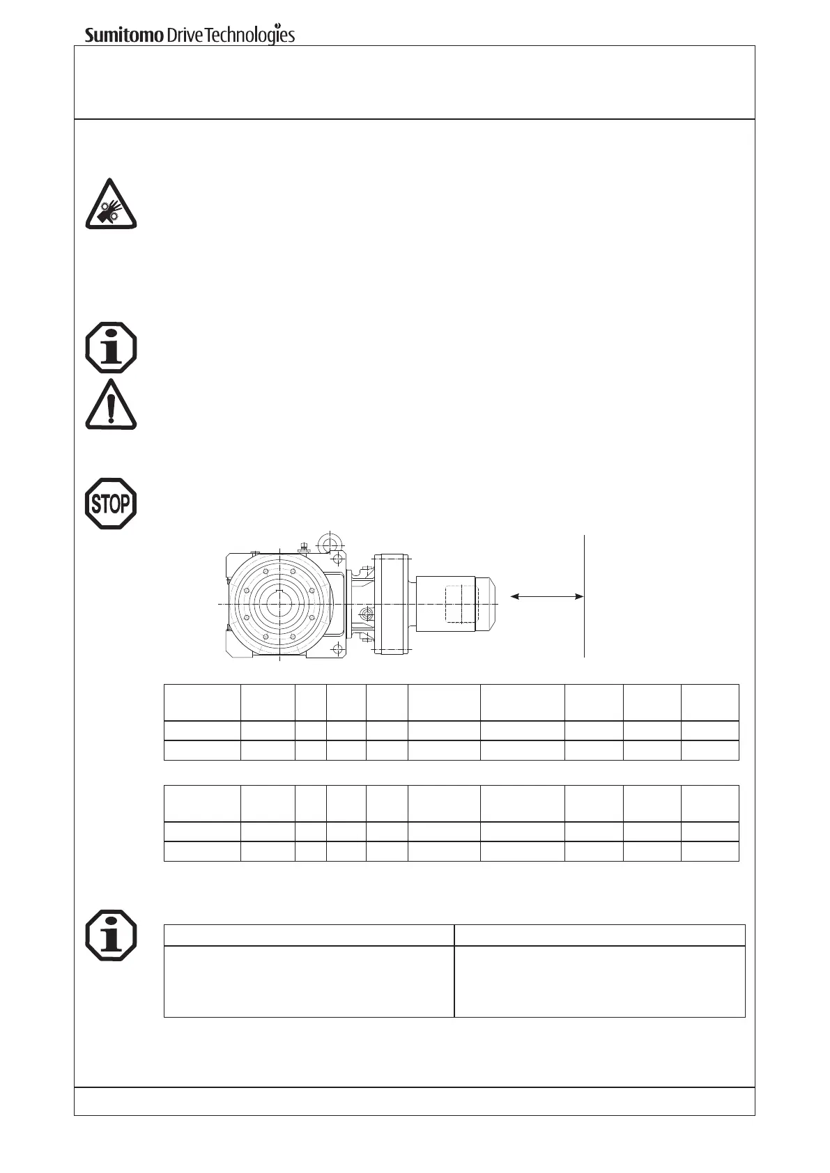
6.3 Installation
Ventilation openings must be kept clear.
For correct cooling the distance FB is the minimum required between the fan cover and the wall.
FA is the minimum clearance required for disassembling the fan cover.
FA or FB
Standard motor
Motor-
Size:
63 - 71 80 90 100 112-132S 132M-160M 160L 180M 180L
FB (mm): 20 20 20 20 20 25 30 30 30
FA (mm): 48 49 52 56 60 75 130 155 170
Brake motor
Motor-
Size:
63 - 71 80 90 100 112-132S 132M-160M 160L 180M 180L
FB (mm): 20 20 20 20 25 25 30 30 30
FA (mm): 61 93 115 121 132 170 220 367 370
6.4 Cable inlet threads sizes
The following thread sizes are suitable for the standard motors
Frame size Conduit thread
63 - 71
80 - 132S
132M - 160
180
1x M16 x 1,5 / 1x M25 x 1,5
2x M25 x 1,5
2x M32 x 1,5
2x M40 x 1,5
Cable glands suitable for the motor protection level must be used.
Any unused cable entries must be closed, to the correct motor protection level.