GDM-FW9010(E) 3-3
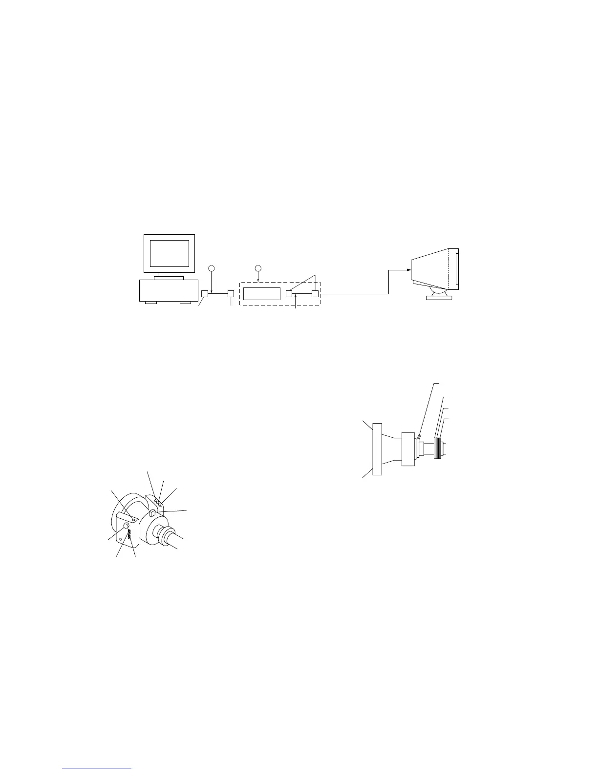
Connect the communication cable of the computer to the connector located on the D board. Run the service software and then follow the instruction.
IBM AT Computer
as a Jig
*The parts above (1 and 2) are necessary for DAS adjustment.
To BUS CONNECTOR
1-690-391-21
Cord,Connection
D-sub
(9 pin [female])
mini Din
(8 pin)
1
A-1500-819-A
Interface Unit
2
Connector
Attachment
Box Unit
4 pin
• Convergence Rough Adjustment
(1) Receive an image of the white crosshatch signals (white lines
on black).
(2) Place the protrusions of the 6-fold poles magnet attached to
the CRT neck upon each other.
(3) Make rough adjustment of the H and V direction convergence
by using 4-fold poles magnet.
H-TRP
YBH
TLH
TLV
APH
XBV
YCH
XCV
Purity
4-pole magnet
6-pole magnet
2-pole magnet
* Set so that the protruding parts of the 2
magnet rings agree with each other.