GDM-FW9010(E) 2-1
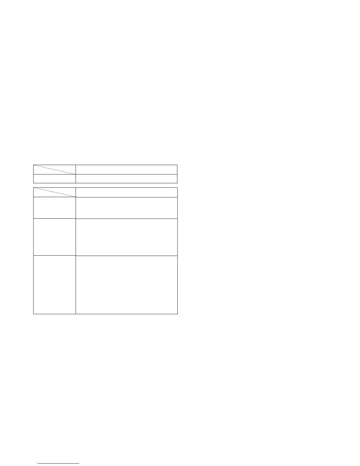
Part Replaced ([)
RV901
SECTION 2
SAFETY RELATED ADJUSTMENT
When replacing or repairing the shown below table, the following
operational checks must be performed as a safety precaution against X-
rays emissions from the unit.
* Confirm one minute after turning on the power.
HV ADJ
HV Regulator
Circuit Check
HV Protector
Circuit Check
Beam Current
Protector Circuit
Check
Part Replaced (])
D Board C901, R923, R924,
R929, R943, T902(FBT)
• Mounted D Board
D Board C922, C926, D912,
D915, D921, Q907,
Q908, R921, R922,
R932, R937, R939,
T902(FBT)
• Mounted D Board
D Board C921, C933, D901,
D913, R920, R928,
R930, 931, T902(FBT)
• Mounted D Board
N Board IC001, R031, R032
• Mounted N Board
a) HV Regulator Circuit Check
1) Enter black crosshatch signal (black on white background), and check
that high voltage is in the specified range.
[Specification]: 28.50 ± 0.10 kV
2) Check that the voltage of D912 cathode on the D board is 29.0 V or
more.
b) HV Protector Circuit Check
1) Enter black crosshatch signal (black on white background).
2) Apply the specified voltage to the D912 cathode on the D board, and
check that high voltage is 0.1 kV or less.
[Specification]: 34.00 + 0.00/– 0.05 V
c) Beam Current Protector Circuit Check
(1st Protector): D Board
1) Apply 4.5 V DC to CN504 0 pin on the D board, and check high
voltage value.
2) Connect constant current source to a section between T902 (FBT) qa pin
and qs pin (GND) on the D board, and check that high voltage checked in
1) lowers by 1.50 kV or more when the specified current flows to the qa
pin.
[Specification]: 2.00 + 0.00/– 0.01 mA
d) Beam Current Protector Circuit Check
(2nd Protector): D Board
1) Connect constant current source to a section between T902 (FBT) qa pin
and qs pin (GND) on the D board, and check that the voltage of CN504 0
pin becomes 0 V or less when the specified current flows to the qa pin.
[Specification]: 1.63 + 0.00/– 0.01 mA