28 SUNFAR E300 SERIES
It is used for defining meaning content of collector open-circuit output terminal OC and relay
output contactor. Inner wiring diagram of collector open-circuit output terminal is shown as fig
6-8. When set function valid, output lower electrical level; when function invalid, output
high-resistance state.
Relay contactor output: when set output function valid, normal open contactor TA-TC connect.
0:During inverter running
When inverter is during running, output valid signal (lower electrical level); output invalid signal
(high-resistance) during stop state.
1:Freq reach
When inverter output freq is approach to setting freq range (confirmed by parameter [F1.13]),
output valid signal (lower electrical level), otherwise, output invalid signal (high-resistance).
R
1
2
D
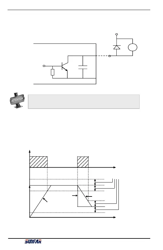
Fig 6-8 Inner wiring of OC output
When add external inductance component (as relay loop), it must be
parallel connection fly-wheel diode D.
Terminal output
Freq
high-resistance
[F1.13]
T
Output freq
Set f req
Output freq
high-resistanc
Fig 6-9 Freq reaching signal
E300 Series Mini-type Integrated Universal Inverter Manual