Functional Details 55
E500 Series Universal Low-Power Inverter
operation of the inverter.
Note: when the grid voltage is too low, the motor’s output torque will reduce.
For occasions with constant power load and constant torque load, excessive low
grid
voltage will cause incease of inverter input current, hence leading to reduction
of inverter operation reliablity.
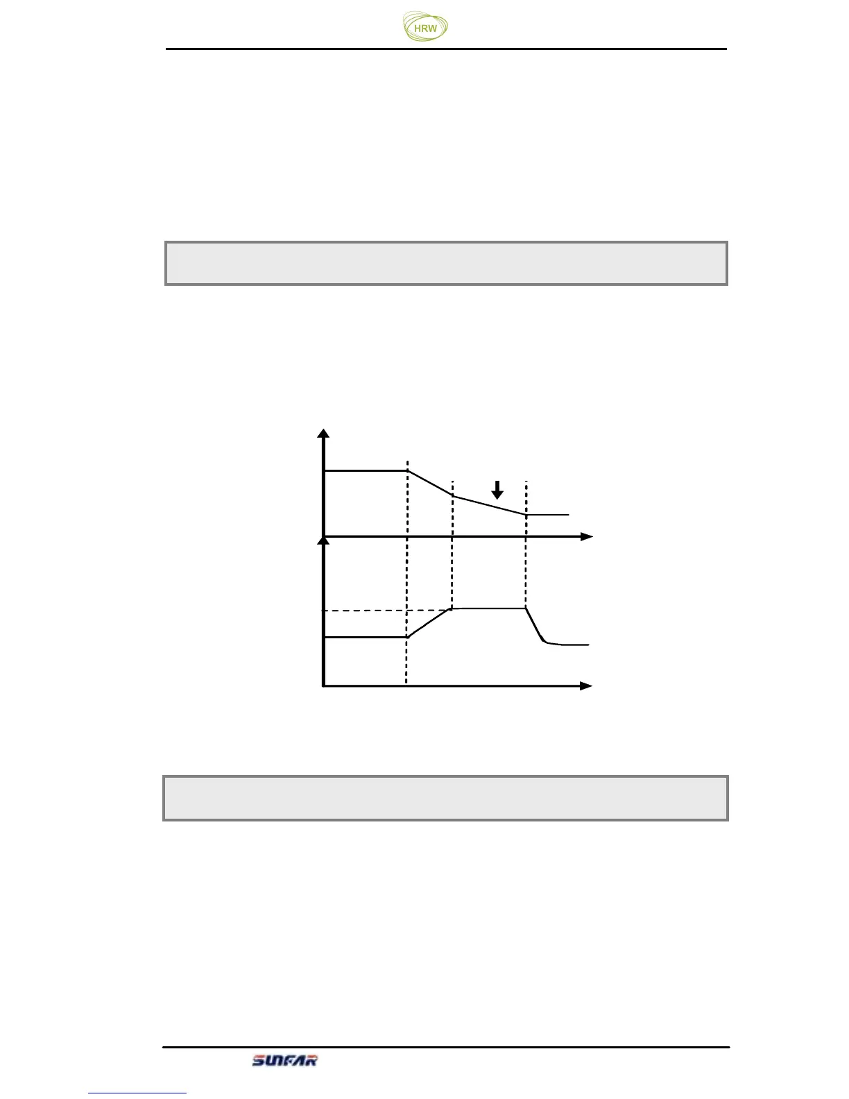
This parameter specifies the threshold value
of voltage stall protection during
motor decelration. When the pumping voltage at the internal DC side of the
Inverter caused by deceleration has exceeded this value, the decerlation time will
be automatically prolonged. See figure 6-16.
This parameter specifies maximum current allowed to be output by the inverter,
which is expressed by the percentage of rated current of the inverter. No watter
what working status (acceleration, deceleration and steady running) the inverter
is at, when the inverter’s output current exceeds the value specified by this
parameter, the inverter will adjust the output frequency to control the current
within the specified range to avoid over current tripping.
Inverter’s control software version number is read only.
F3.12 Overvoltage limiting action level Setting range: 350 ~400V/700 ~800V
[F3.12]
频率
时间
时间
减速时间调整
直流电压
Figure 6-16 Voltage Stall Protection during Deceleration
F3.13 Current amplitude limiting level Setting range: 150 ~ 250(
%
)
Frequency
DC voltage
Time
Deceleration time adjustment
Time
[F3.12]