18
• Expansion bolt (in the delivery scope)
• Tapping screw (in the delivery scope)
• Screwdriver (beyond the delivery scope)
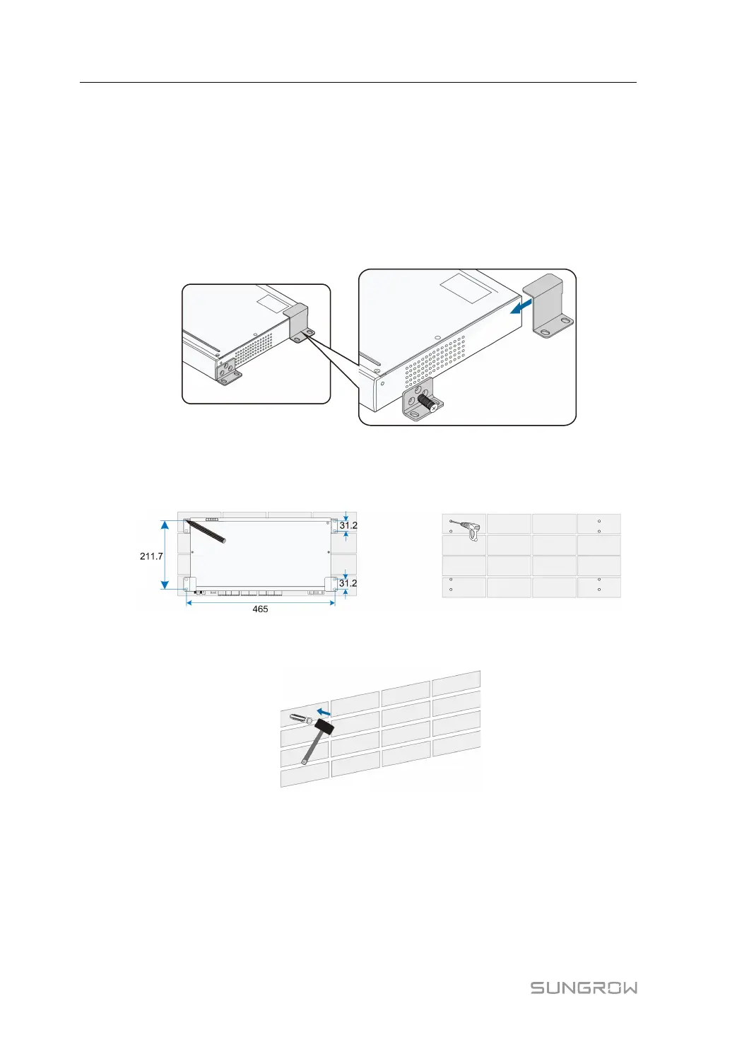
IInnssttaallll MMoouunnttiinngg EEaarrss aanndd BBoottttoomm SSuuppppoorrtteerrss
Anchor the mounting ears and bottom supporters to the Logger3000 with supplied
M4x8 cross recessed countersunk head screws. The fastening torque is 1.8-2.4N·m,
and the anchoring method is as follows:
MMoouunntt tthhee LLooggggeerr33000000 ttoo tthhee WWaallll
step 1 Mark positions for drilling holes on the installation wall. Drill the holes with a hammer drill
of φ6mm. (Note: Reserve sufficient clearances around the Logger3000.)
step 2 Insert the expansion sleeve into the drilled hole, and make it completely embedded in
the wall with a rubber hammer.
step 3 Insert the tap screw and mounting ear successively into the expansion sleeve, to fix the
Logger3000 onto the wall.
6 Mechanical Installation User Manual