User Manual 5 Electrical Connection
•
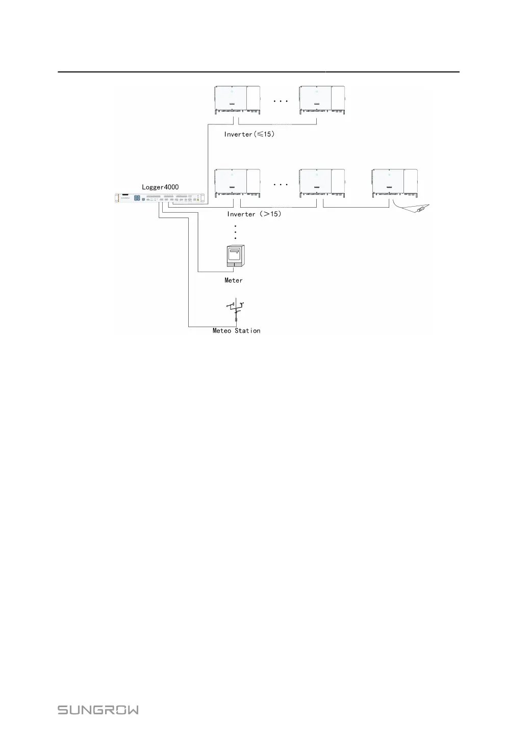
The Data Logger supports 7 RS485 buses and 300 devices at most. Each RS485 bus
supports 80 devices at most.
•
Devices of different types must be connected to different RS485 communication ports of
the Data Logger. For example, the transformer and the inverter should be connected to
different RS485 communication ports of the Data Logger.
•
The address of each device on the RS485 bus should be within the set address range
(1 to 246) of the Data Logger, and duplicate addresses are not allowed. Otherwise,
communication failure occurs.
•
Serial port parameters of each device on the RS485 bus should be consistent with those
of the Data Logger. The serial port parameters include baud rate, data bit, stop bit, and
check bit.
23
 Loading...


