5 Electrical Connection User Manual
Connection Method
step 1 Lead the RS485 communication cable from the inverter to the wiring area of the Data Logger.
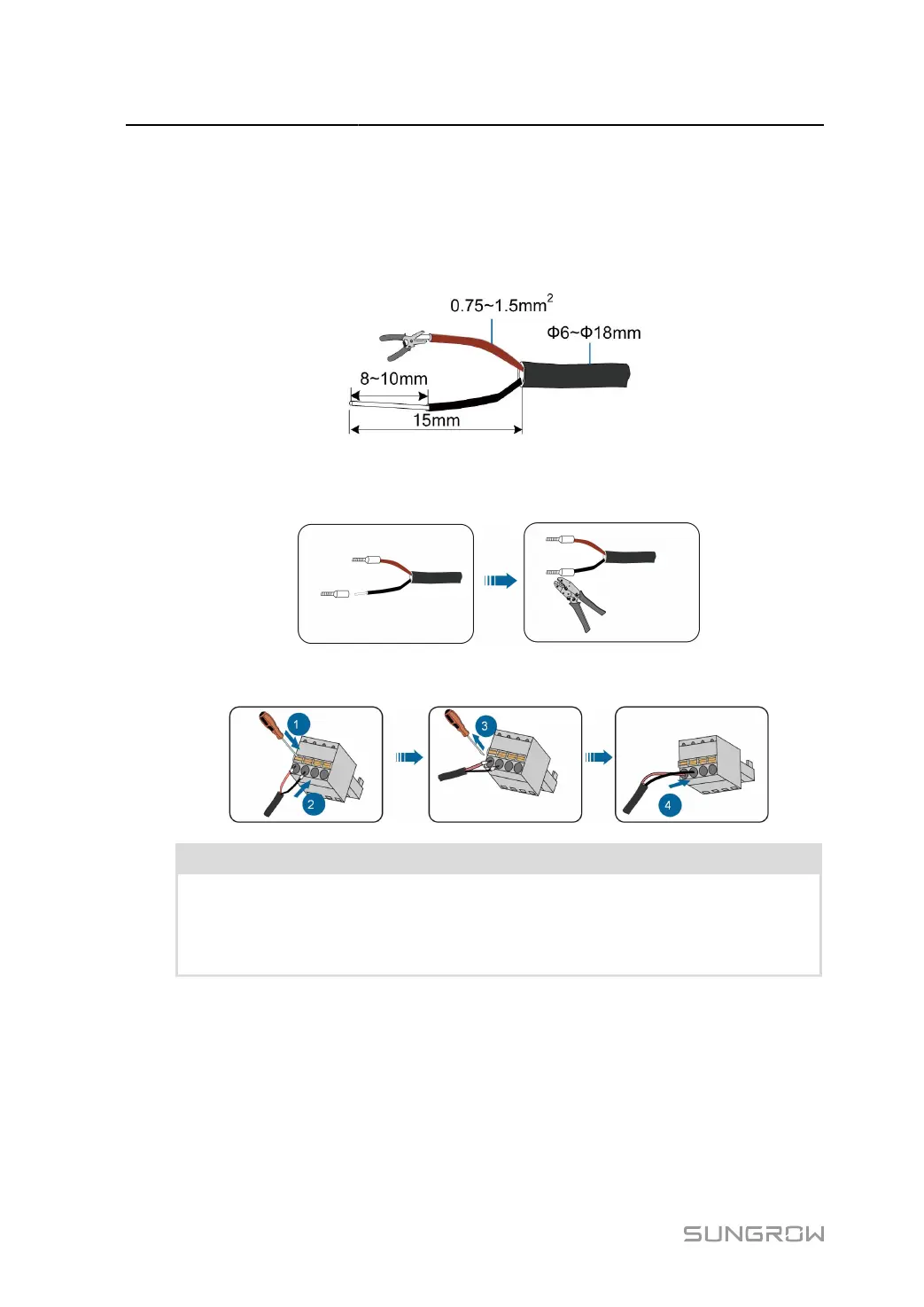
step 2 Strip the protection layer of the communication cable with a wire stripper. Cable specification and
stripped length are as follows.
step 3
Install appropriate cord end terminals on the communication cables after removing the protective
layer, and use a crimping tool to securely crimp them.
step 4
Crimp the wiring terminals.
NOTICE
• Connect RS485A to port A and RS485B to port B.
•
The RS485 communication cable must be the shielded twisted pair with the
shielding layer single-point grounded.
24
 Loading...


